GE Fanuc PLC

  1. Home
  2. Products
  3. GE Fanuc PLC
  4. GE IC200PWB001 Extended Power Supply Booster Carrier for VersaMax I/O Systems
GE IC200PWB001 Extended Power Supply Booster Carrier for VersaMax I/O Systems

GE IC200PWB001 Extended Power Supply Booster Carrier for VersaMax I/O Systems

0.0
Points

Brand:GE Fanuc PLC
Item No.:GE IC200PWB001
Product Origin: USA
Product Dimensions:133.4 × 66.8 × 70 mm
Product Weight:0.11 kg
Payment:T/T, Western Union, Credit Card
Goods_stock:15
Shipping Port:Xiamen, China
Lead Time:1-3 Days
Condition:Brand New And Original
Warranty:1 Year
Certificate:COO

Add to cart

IC200PWB001 - 3IC200PWB001 - 4IC200PWB001 - 2IC200PWB001 - 1

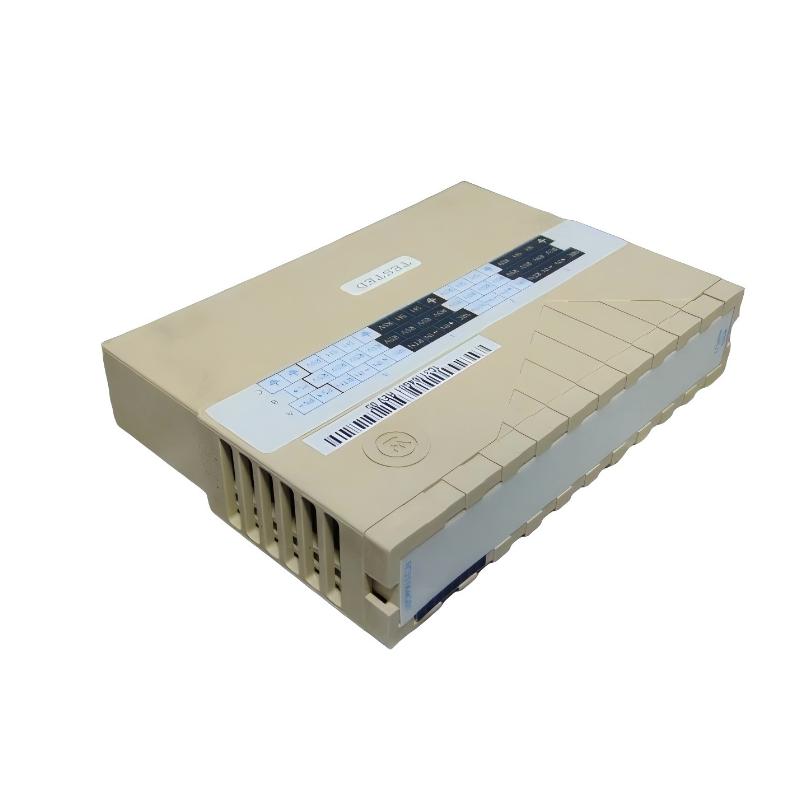
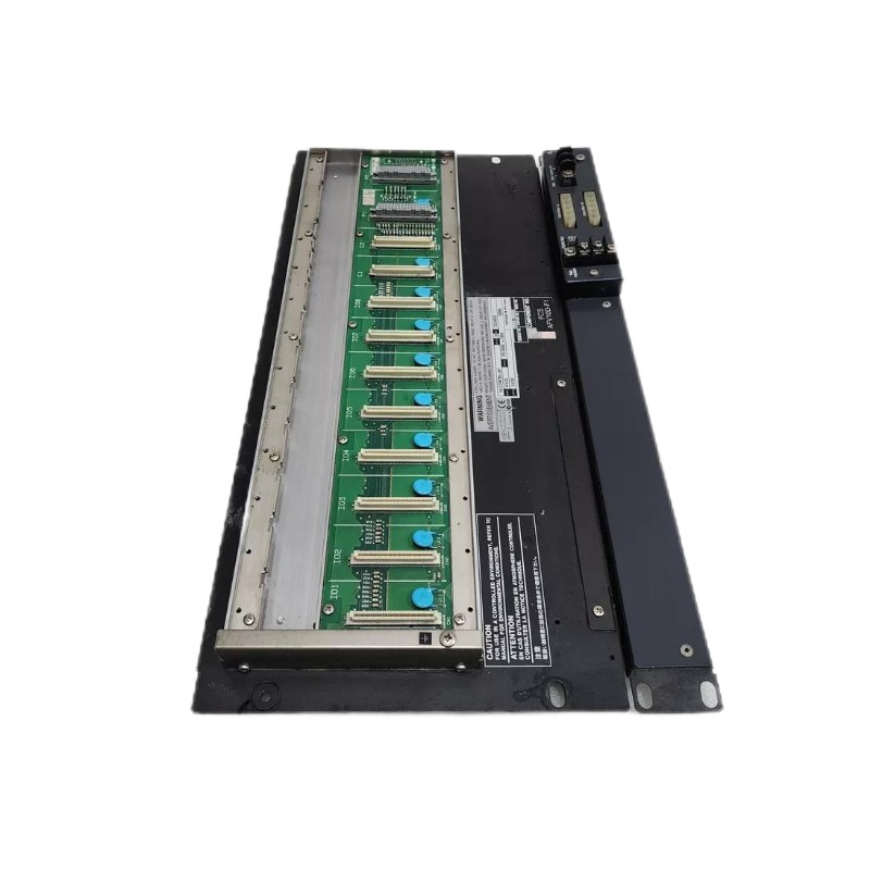
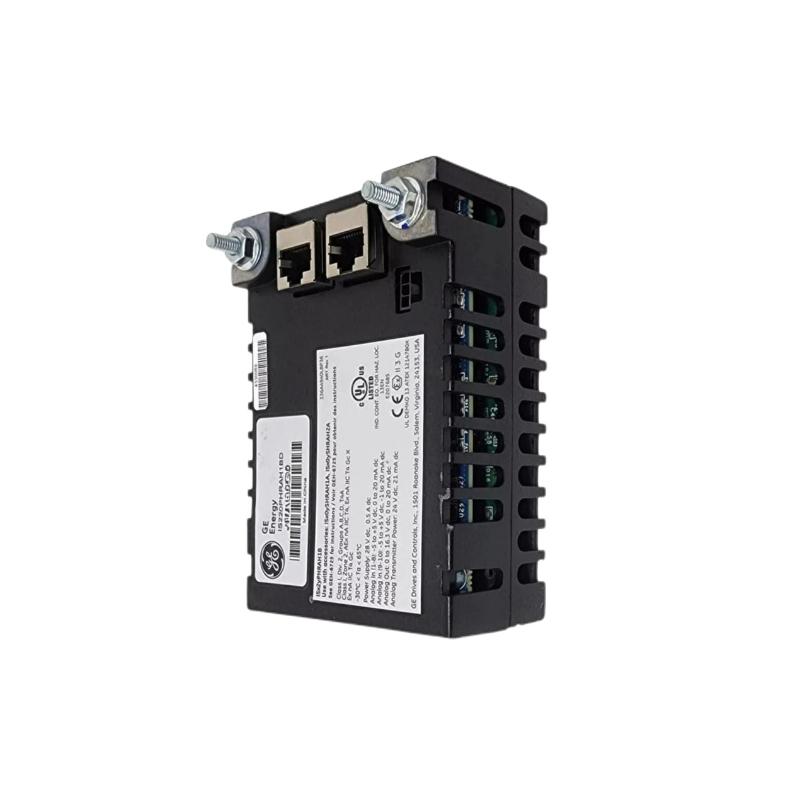
The GE IC200PWB001 Power Supply Booster Carrier is a purpose-built accessory for GE’s VersaMax distributed I/O architecture, designed to extend and stabilize power distribution across larger or high-density I/O installations. Rather than supplying power itself, this module provides a robust carrier platform that allows an additional power supply to be integrated downstream, ensuring modules further along the I/O chain receive reliable and consistent power. Its tool-free DIN rail mounting, rugged construction, and clear status indicators make it a dependable choice for system integrators and control engineers working in demanding industrial environments.


Technical Specifications

ParameterDescription
Module TypePower Supply Booster Carrier
PurposeDistributes power from an additional power supply to I/O modules
LED IndicatorsPWR (booster supply status), OK (system & booster status)
MountingStandard DIN rail (7.5 mm × 35 mm rail)
Approx. Dimensions (H × W × D)~133.4 × 66.8 × 70 mm
Approx. Weight~0.11 kg (~0.31 lbs)
FinishConductive, corrosion-resistant surface
CompatibilityWorks with VersaMax power supplies and I/O modules
Operating ConceptShares external supply between CPU/NIU and booster power
InstallationSnap-on, tool-free DIN-rail mounting

Note: The booster carrier itself does not provide DC conversion or regulation; it requires an external power supply to be installed on the booster to energize downstream modules.


Recommended Related Models

ModelDescription
IC200PWR001VersaMax DC power supply module
IC200PWR101AC input power supply for VersaMax
IC200MDL74016-point DC digital input module
IC200MDL742H32-point DC output module

Popular GE VersaMax System Components

Product CategoryRepresentative Models
PLC CPUsIC200CPU001, IC200CPU002
Network InterfacesIC200PNS001 (PROFINET), IC200ETH001 (Ethernet)
I/O CarriersIC200CHS010, IC200CHS044
Analog I/OIC200ALGxxx series


Applications

The IC200PWB001 Booster Carrier is used wherever extended I/O power distribution is required in a VersaMax installation:

  • Large Control Racks: Drives additional modules far from the primary CPU power source

  • High-Load I/O Systems: Ensures sufficient power capacity for numerous field I/O modules

  • Distributed Cabinet Designs: Allows flexible placement of power supplies within extended I/O strings

  • Industrial Automation Lanes: Packaging, material handling, and process control stations with dense I/O arrays

This booster carrier is ideal for systems where the total module count and associated current draw exceed the capacity of a single power supply.


Advantages

  • Extended power distribution: Supports a second power supply to reach modules further along the I/O chain

  • Snap-on DIN-rail mounting: Tool-free installation saves time during panel build or maintenance

  • LED status feedback: “PWR” and “OK” LEDs provide at-a-glance power and system health status

  • Rugged industrial finish: Corrosion-resistant construction ensures durability even in harsh environments

  • VersaMax compatibility: Designed specifically to integrate with VersaMax power supplies and I/O modules 


Technical FAQs

  1. What is the main role of the IC200PWB001?
    It serves as a power supply booster carrier to extend power distribution in a VersaMax I/O chain.

  2. Does the booster carrier provide its own DC power?
    No — an external power supply must be installed on the booster to energize downstream modules.

  3. How is the module mounted?
    It uses DIN rail mounting (7.5 mm × 35 mm rail) with a snap-on installation.

  4. What do the LED indicators represent?
    “PWR” indicates the status of the attached booster supply; “OK” confirms the CPU/NIU and booster are functioning properly.

  5. Can it be used with any VersaMax power supply?
    Yes — it’s compatible with standard VersaMax DC and AC power supply modules.

  6. Where should an external power supply be mounted?
    On the booster carrier itself, enabling power to modules positioned to the right of the booster.

  7. Does this module support hot-swapping?
    Many installations allow module replacement with minimal downtime, but recommended procedures vary with system design.

  8. Is the booster required for all VersaMax installations?
    Only in larger or high-current systems where a single power supply cannot support the total module load.

  9. Does it affect communication or control performance?
    No — it strictly manages power distribution and does not influence data or I/O signaling.

  10. How should the DIN rail be prepared?
    It should be electrically grounded to ensure EMC protection and reliable operation.


Look forward to your comments!Comment
Latest comments
Tags:
Need Assistance? Chat with Us on WhatsApp!
Need Assistance? Click to Inquire
Back to top