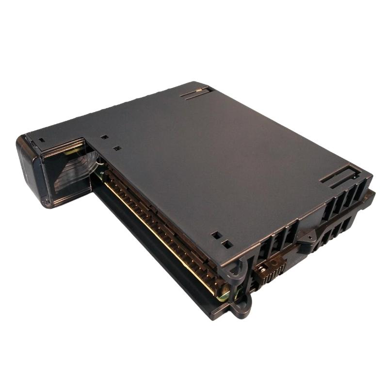
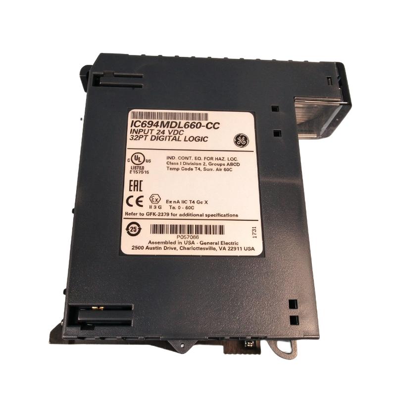
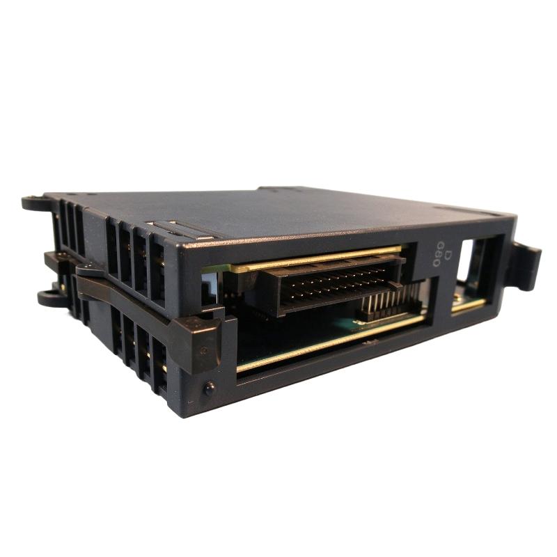
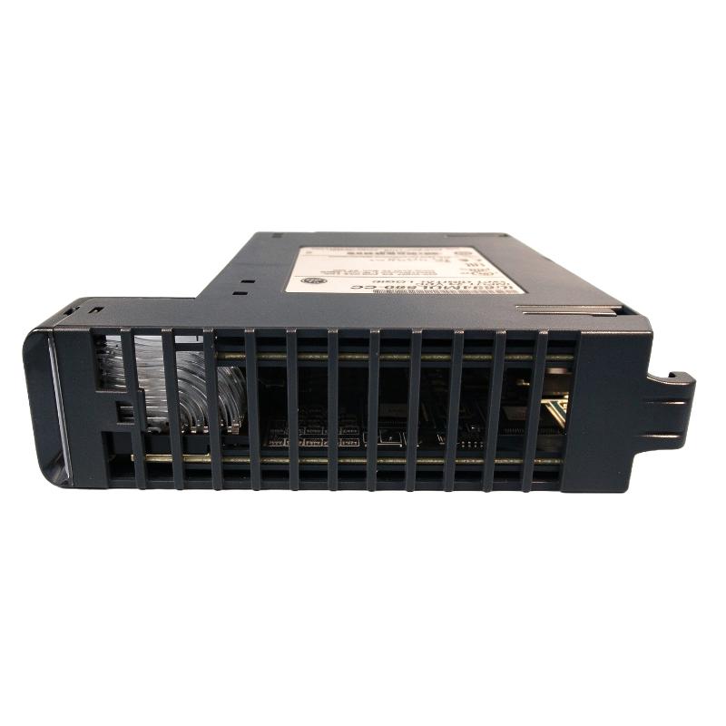
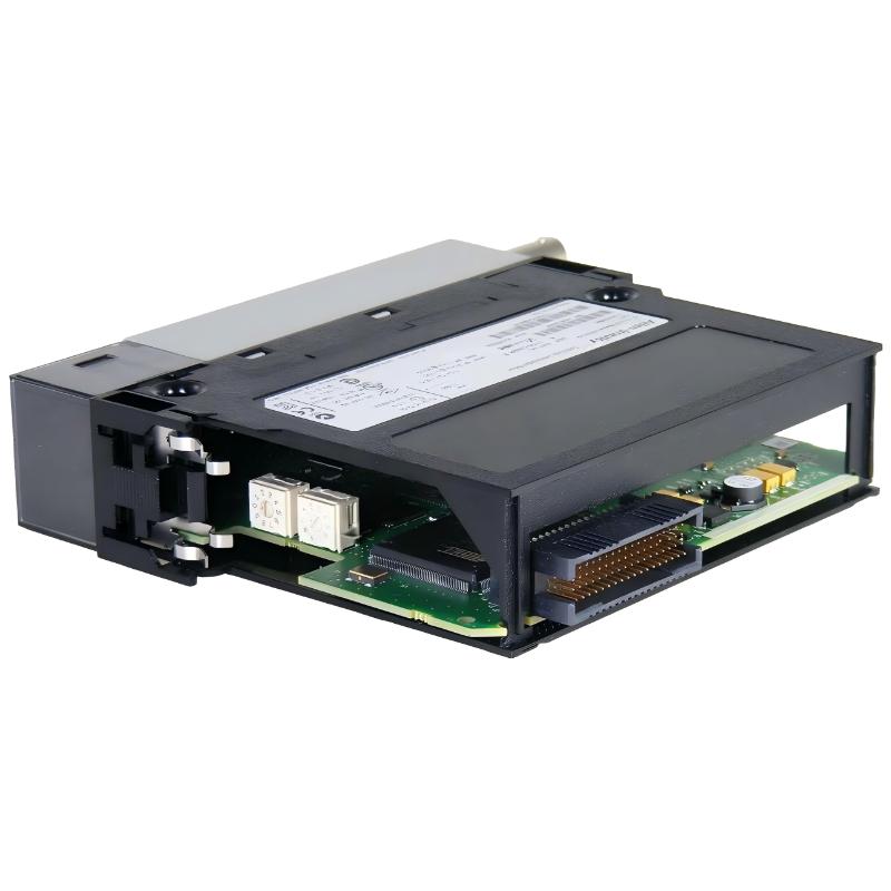
Brand:GE Fanuc PLC Item No.:IC695MDL660 Product Origin:USA Product Dimensions:145 x 34 x 140 mm Product Weight:0.25 kg Payment:T/T, Western Union, Credit Card Goods_stock:15 Shipping Port:Xiamen, China Lead Time:1-3 Days Condition:Brand New And Original Warranty:1 Year Certificate:COO
The GE IC695MDL660 Digital Input Module is intended for use in industrial control environments where discrete field signals must be collected and processed by a PLC. Digital input modules provide the interface between field-level devices and controller logic, allowing automation systems to monitor equipment states and coordinate operating sequences.
In manufacturing and process control applications, dependable input acquisition is essential for machine sequencing, status monitoring, alarm handling, and equipment coordination. Selecting the correct module helps ensure that the electrical characteristics of field devices align with the requirements of the control system.
When purchasing the IC695MDL660, confirm the exact catalog number and condition of the supplied unit. For replacement projects, also verify PLC hardware compatibility, electrical input specifications, terminal accessories, and configuration requirements before commissioning.
Technical Specifications
Parameter
Specification
Brand
GE
Model
IC695MDL660
Product Type
Digital Input Module
Product Category
PLC Input Module
Dimensions
145 × 34 × 140 mm
Weight
0.25 kg / 0.55 lb
Application
Discrete signal acquisition and PLC monitoring
Installation
Compatible control-system hardware
Input Voltage
Verify against the module nameplate and technical documentation
Input Channels
Confirm from the exact product documentation
Electrical Connection
Verify terminal and backplane requirements
System Compatibility
Confirm PLC platform and configuration support
The dimensions and weight listed above are based on the supplied product information. Electrical ratings, channel count, and configuration details should be verified before ordering or installation.
Recommended Related Models
The following GE automation product families may be relevant when planning PLC input-system maintenance or expansion. They are not confirmed direct replacements for the IC695MDL660.
Model
Product Type
Selection Consideration
GE IC695MDL645
Digital Input Module
Verify electrical characteristics and system compatibility
GE IC695MDL650
Digital Input Module
Check input specifications and supported configuration
GE IC695MDL664
Digital Input Module
Confirm channel requirements and installation compatibility
GE IC695MDL670
Digital Input Module
Compare electrical ratings and system requirements
Before selecting an alternative, confirm the full catalog number, input voltage, channel arrangement, terminal compatibility, and PLC hardware support.
Popular Related Models
Other GE automation components may be relevant to maintenance, expansion, or replacement planning for PLC-based control systems.
Model
Product Type
Typical Role
GE IC695CPU310
CPU Module
PLC control and logic processing
GE IC695PSD040
Power Supply Module
Power distribution for compatible control hardware
GE IC695ETM001
Ethernet Interface Module
Industrial Ethernet communication
GE IC695ALG600
Analog Input Module
Acquisition of analog field signals
These models serve different functions and should not be treated as interchangeable with the IC695MDL660. Confirm the required hardware platform and system configuration before procurement.
Applications
The GE IC695MDL660 Digital Input Module is designed for industrial automation systems that require reliable acquisition of digital field signals. As part of a PLC-based control architecture, a digital input module receives discrete status signals from field devices and makes this information available to the controller for logic processing and operational monitoring.
Typical application areas include:
PLC-Based Machine Control: Collecting discrete signals from push buttons, selector switches, limit switches, and other field devices.
Industrial Process Automation: Monitoring equipment status and discrete process conditions in automated production environments.
Equipment Interlocking: Providing input signals used by control logic to coordinate machine operations and implement interlock sequences.
Manufacturing Systems: Supporting automated assembly lines, packaging equipment, and material handling systems.
System Maintenance and Upgrades: Serving as a replacement or spare component in compatible GE automation installations, subject to hardware and configuration verification.
The module's suitability for a particular application should be confirmed against the installed PLC platform, electrical input requirements, and system configuration.
Advantages
Reliable Signal Acquisition: Supports the collection of discrete field signals for PLC control and monitoring functions.
Integration with Automation Systems: Can be considered for compatible GE control architectures where the module's hardware requirements are satisfied.
Centralized Control: Enables field-device status information to be incorporated into PLC logic, alarms, and sequencing operations.
Maintenance Flexibility: Keeping a suitable spare module available can help reduce troubleshooting delays and support maintenance planning.
Compact Physical Design: The supplied dimensions of 145 × 34 × 140 mm make it easier to evaluate the module's installation requirements.
Industrial Application Potential: Suitable for consideration in discrete control applications where dependable input monitoring is required.
Before installation, verify the exact catalog number, terminal arrangement, input voltage, channel configuration, and compatibility with the target PLC system.
Technical FAQs
Q1: What is the primary function of the GE IC695MDL660?
The IC695MDL660 is identified as a digital input module. Its primary role is to receive discrete electrical signals from field devices and make their states available to the PLC control system.
Q2: What field devices can a digital input module monitor?
Depending on its electrical specifications, a digital input module may monitor devices such as push buttons, selector switches, limit switches, auxiliary contacts, and other discrete-output sensors. Confirm that the field-device signal matches the module's input requirements.
Q3: How does the module communicate input status to the PLC?
The module interfaces with the supported PLC hardware through its designated backplane or system connection. The controller reads the input states and uses them within the configured control logic.
Q4: What should be checked before connecting field wiring?
Verify the input voltage, signal polarity where applicable, common-terminal arrangement, channel assignments, grounding requirements, and terminal wiring diagram. Incorrect wiring can cause unreliable signals or hardware damage.
Q5: How can incorrect input readings be diagnosed?
Check the field-device output, supply voltage, wiring continuity, terminal connections, module indicators, controller diagnostics, and input configuration. Comparing the field signal with the PLC's reported input state can help isolate the problem.
Q6: Does the IC695MDL660 require PLC configuration?
The module generally needs to be recognized and configured within the supported automation system. Confirm the required hardware configuration, software version, and any module-specific parameters using the applicable system documentation.
Q7: Can the module be used in a safety-related control circuit?
Do not assume that a standard digital input module provides a certified safety function. Safety applications require hardware specifically approved for the required safety level and a validated system design.
Q8: What environmental factors should be considered during installation?
Consider operating temperature, humidity, electrical noise, vibration, enclosure protection, and cabinet ventilation. The permitted limits must be confirmed from the manufacturer's specifications for the exact module.
Q9: What precautions should be taken when replacing the module?
Confirm the full catalog number and hardware revision, document the existing wiring, check the PLC configuration, and follow the system's shutdown and electrical isolation procedures. Verify operation after replacement before returning the equipment to service.
Q10: How can long-term reliability be maintained?
Use correct wiring practices, keep terminals secure, control cabinet temperature, prevent contamination, and inspect diagnostic indicators during routine maintenance. Maintain accurate configuration records and keep a verified compatible spare where operational continuity is important.