ABB 07 EA 63 R1 / GJV3074353R1 Analog Input Module Installation Guide
ABB 07 EA 63 R1 analog input module installation faults are most commonly caused by incorrect field wiring, improper signal range configuration, or insufficient grounding, rather than electronic component failure. Proper installation ensures accurate analog signal acquisition from sensors into ABB AC500/800M PLC or distributed control systems.
ABB 07 EA 63 R1 Module Role in Control System
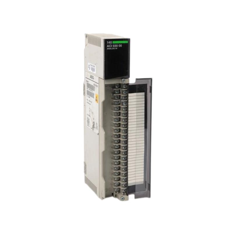
The ABB 07 EA 63 R1 (GJV3074353R1) module is a high-precision analog input interface, designed to convert 4–20 mA, 0–10 V, or RTD signals from field devices into the ABB PLC system. It supports:
- 8 differential analog input channels
- Isolation between channels and power supply
- Onboard filtering for signal noise reduction
- Integration with AC500 or AC800M systems for process automation
Field Observation: In one water treatment plant, unstable flow readings were traced to incorrectly shielded 4–20 mA cables. Proper shielding and separation from power lines solved the issue immediately.
Pre-Installation Checks
Mechanical Checks
- Module slots clean, rails free of debris
- Rack mounting free from vibration
- Adequate airflow around the module for heat dissipation
Electrical Checks
- DC power supply stable within 24 ± 2 V
- Grounding resistance <1 Ω
- Signal lines properly shielded and twisted-pair for current loops
Case Note: On a chemical plant skid, intermittent analog spikes were eliminated after grounding the PLC rack at a single point, avoiding ground loops.
Wiring and Signal Connection
Analog Signal Wiring
- Connect sensors according to channel mapping (AI1–AI8)
- For current loops (4–20 mA), ensure proper termination resistor (typically 250 Ω)
- For voltage signals (0–10 V), ensure high-impedance input configuration
Shielding & Separation
- Maintain distance from high-current motor cables
- Tie shields at single point to module ground
- Avoid routing near variable frequency drives
Observation: Voltage inputs showed ±0.5 V noise when routed parallel to VFD cables. Re-routing and grounding reduced noise to ±20 mV.
Commissioning Strategy
Step 1: Static Signal Verification
- Inject known signals (4 mA, 12 mA, 20 mA)
- Verify module readings in engineering software
- Check LED indicators for channel status
Step 2: Dynamic Signal Validation
- Connect real process sensors
- Observe signals under load
- Compare against calibrated reference instruments
Case: A flow sensor reading fluctuated ±10% until wiring was corrected; after proper shielded twisted pair installation, accuracy improved to ±1%.