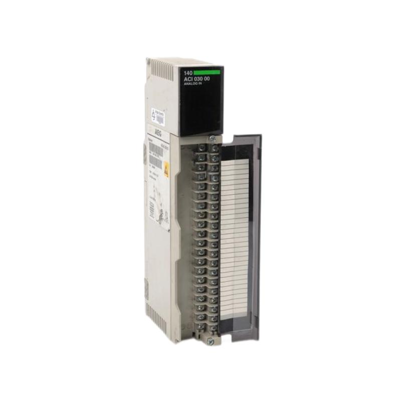
Schneider 140ACI03000 Analog Input Module Installation Guide for Modicon Quantum PLC Systems
Schneider 140ACI03000 analog input module installation issues are most commonly caused by incorrect 4–20 mA loop wiring, poor shield grounding, or channel configuration mismatch, rather than module hardware failure. In Modicon Quantum PLC systems, this module acts as a high-precision 8-channel differential analog signal acquisition unit, converting field instrument signals into stable digital values for process control.
Schneider 140ACI03000 Role in Quantum PLC Analog Architecture
The Schneider 140ACI03000 is an 8-channel differential analog input module used in Modicon Quantum automation platforms.
Core functions:
- Acquisition of 4–20 mA and 1–5 V analog signals
- Conversion of field sensor signals (pressure, flow, level, temperature) into PLC data words
- High noise immunity via differential input design
- Electrical isolation between channels and backplane (up to 1000 V DC)
Typical application structure:
-
Field transmitter (pressure / flow / temperature)
→ Signal cable (shielded 4–20 mA loop)
→ 140ACI03000 analog input channel
→ Quantum backplane
→ PLC control logic
In one water treatment plant case, unstable flow readings were traced not to sensor drift but to floating shield termination on multiple analog loops, causing intermittent channel fluctuation.
Installation Conditions (Critical Engineering Requirements)
1. Signal Type Verification (Most Important Step)
The 140ACI03000 supports:
- 4–20 mA current loop
- 1–5 V voltage input
Field engineering rule:
- Never mix voltage and current configuration on the same channel group
- Ensure transmitter output type matches PLC input configuration
A common field failure occurs when a 4–20 mA transmitter is mistakenly terminated as voltage input, producing unstable readings near 20 mA range.
2. Wiring and Loop Integrity
Each channel uses differential input architecture, meaning:
- Two-wire or loop-powered transmitters supported
- No shared return between channels
- Each input is electrically isolated from bus and adjacent channels
Field best practices:
- Use shielded twisted pair for each signal loop
- Terminate shield at single earth point only
- Avoid daisy-chaining analog commons
In one chemical dosing system, cross-channel interference occurred because multiple shields were grounded at both ends, creating ground loops.
3. Power and Backplane Stability
- Module draws approx. 240 mA from backplane
- Ensure rack power supply is stable under full I/O load
- Avoid voltage dips during motor start events in shared cabinets
Field observation: analog signal jitter often appears during compressor startup due to shared DC supply instability.
Installation Procedure (Field Engineering Practice)
Step 1: Rack and Slot Preparation
- Insert module into correct Quantum rack slot
- Ensure full backplane engagement
- Verify no bent pins or partial insertion
Step 2: Field Wiring Connection
- Connect 4–20 mA loop or 1–5 V signal per channel
- Maintain polarity consistency
- Tighten terminal connections to prevent micro-disconnections
A loose terminal in one refinery caused intermittent pressure spikes reading from 6.2 to 14.8 bar without actual process variation.
Step 3: Shielding and Grounding
- Ground shield at PLC cabinet end only
- Keep analog cable away from VFD output cables
- Maintain minimum separation from power lines
Step 4: Channel Verification
- Check LED status per channel
- Confirm raw value stability in PLC register
- Validate scaling configuration (engineering units)
Commissioning Strategy (Engineering Logic)
Step 1: Static Signal Test
- Inject stable 4–20 mA signal using calibrator
- Verify linear response across full scale
- Check channel-to-channel consistency
Step 2: Process Simulation Test
- Simulate real transmitter behavior
- Observe filtering response (15 Hz low-pass behavior)
- Confirm stable readings under slow signal variation
Step 3: Load Environment Validation
- Run system under full plant operation
- Monitor analog drift during motor start/stop cycles
- Verify immunity to EMI disturbances
In one paper mill, analog noise spikes were eliminated only after rerouting signal cables away from inverter cabinets.