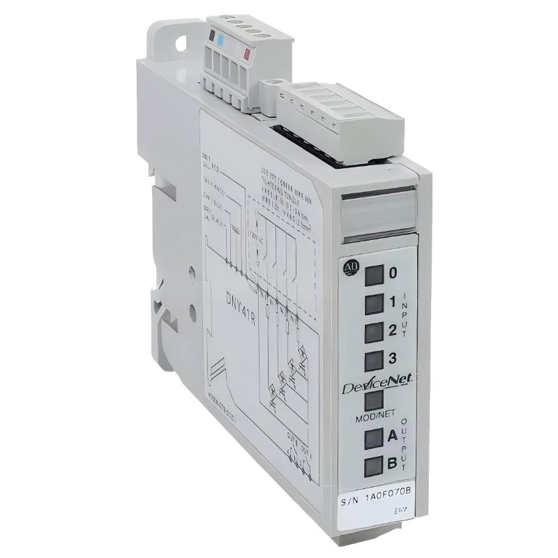
Allen-Bradley 100-DNY41R DeviceNet Starter Auxiliary Installation Guide for Distributed Motor Control Systems
Allen-Bradley 100-DNY41R DeviceNet starter auxiliary installation issues are usually caused by incorrect DeviceNet node configuration, improper input wiring on field devices, or unstable 24V auxiliary power supply, rather than failure of the module itself. In Bulletin 100 distributed starter systems, this compact module acts as a local I/O + communication interface, linking pushbuttons, contactors, and overload feedback directly into the DeviceNet network.
Allen-Bradley 100-DNY41R Role in DeviceNet Distributed Starter Architecture
The 100-DNY41R is a DeviceNet Starter Auxiliary (DSA) module designed to reduce hardwiring between field devices and PLC systems. It provides:
- 4 discrete AC inputs (field device status signals)
- 2 relay outputs (auxiliary control switching)
- DeviceNet communication node interface
- Local distributed motor control logic support
In a typical motor control system, it connects:
- Motor starter auxiliary contacts
- Overload relay status
- Limit switches or selector switches
- DeviceNet master (PLC or scanner module)
Field observation: In one conveyor system upgrade, motor feedback signals were missing in PLC diagnostics. The root cause was not PLC failure but a misconfigured DeviceNet MAC ID duplication on two 100-DNY41R nodes.
Allen-Bradley 100-DNY41R Installation Preparation (Critical Engineering Checks)
Electrical Preconditions
- Stable 24V DC power supply for DeviceNet node
- Ripple <100 mV recommended
- Proper DeviceNet trunk and drop line separation
- Correct termination resistors at both ends of network
Field experience shows that unstable 24V supply often causes intermittent node dropout, especially during motor starting events.
DeviceNet Network Preconditions
- Unique MAC ID for each node (no duplicates allowed)
- Correct baud rate matching (125k / 250k / 500k)
- Proper CAN_H / CAN_L polarity verification
- Shield grounded at single point only
In one packaging plant, repeated “node offline” alarms were traced to reversed CAN wiring on a single 100-DNY41R module.
Allen-Bradley 100-DNY41R Wiring and Field Connection Logic
Input Wiring (4 Channels)
Typical input sources include:
- Motor starter auxiliary contacts
- Push buttons (Start/Stop)
- Limit switches
- Overload relay contacts
Input behavior:
- ON-state voltage range defines valid signal detection
- LED indicators provide immediate status feedback per channel
Output Wiring (2 Relay Outputs)
Relay outputs can be used for:
- Starter coil energization
- Alarm signaling
- Interlocking logic between devices
Relay characteristics:
- Up to 240V AC / 30V DC switching
- Suitable for inductive loads with suppression recommended
Field case: In one water pumping station, relay chattering occurred due to missing suppression diode on contactor coil. After adding suppression, switching stability became fully reliable.
Installation Procedure (Field Engineering Practice)
Step 1: Physical Mounting
- Mount on 35 mm DIN rail
- Ensure module is firmly locked without vibration play
- Maintain spacing from high-heat components
Step 2: DeviceNet Connection
- Connect CAN_H / CAN_L / Shield correctly
- Ensure trunk line continuity
- Install termination resistors at both network ends
Step 3: Address Configuration
- Set unique MAC ID using rotary switches or software tool
- Confirm no duplication in DeviceNet network scan
- Verify node appears in scanner diagnostics
Step 4: Functional Verification
- Check input LED response from field devices
- Trigger starter sequence and confirm relay output response
- Monitor DeviceNet communication status in PLC
Commissioning Strategy (Engineering Field Logic)
Cold Start Validation
- Confirm node online status
- Verify all input channels respond correctly
- Check DeviceNet scan consistency
Load Simulation Test
- Start motor system under controlled conditions
- Monitor relay activation timing
- Observe network stability during inrush current events
Dynamic Stress Test
- Run multiple motors simultaneously
- Check for node dropout under EMI conditions
- Validate communication consistency under load variation
In one steel plant, intermittent node loss occurred only during large motor startup. Root cause was EMI coupling into unshielded DeviceNet drop cable.