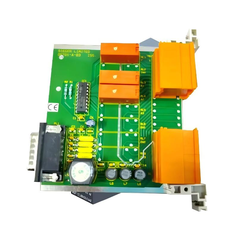
Honeywell 05701-A-0327 Fault Troubleshooting Guide (Relay Chatter & False Alarm Diagnosis)
Honeywell 05701-A-0327 faults are frequently misdiagnosed as sensor or controller issues, while field evidence shows most failures originate from relay contact instability, grounding loops, or backplane vibration effects.
Honeywell 05701-A-0327 Fault Symptoms in Field Operation
Common symptoms include:
- Intermittent A1/A2 relay activation without gas change
- Relay “chattering” during motor startup
- False fault indication on control panel
- Channel instability across multiple cards
- Delayed alarm reset after signal normalization
In one petrochemical facility, repeated false alarms occurred every time a compressor started. Sensor readings were stable, confirming the issue was downstream in the relay control path.
Field Diagnostic Logic for Honeywell 05701-A-0327
Engineers typically apply a relay-first diagnostic approach.
1. Signal Input Validation (4–20 mA Path)
- Stable loop current → sensor healthy
- Fluctuating current → wiring or EMI issue
- Sudden drop → open circuit or connector failure
In a refinery case, loop current remained stable while relay output flickered, confirming a downstream control card issue.
2. Relay Output Stability Check
Using multimeter or logic analyzer:
- Check relay coil activation stability
- Observe contact bounce during switching
- Identify unintended rapid toggling
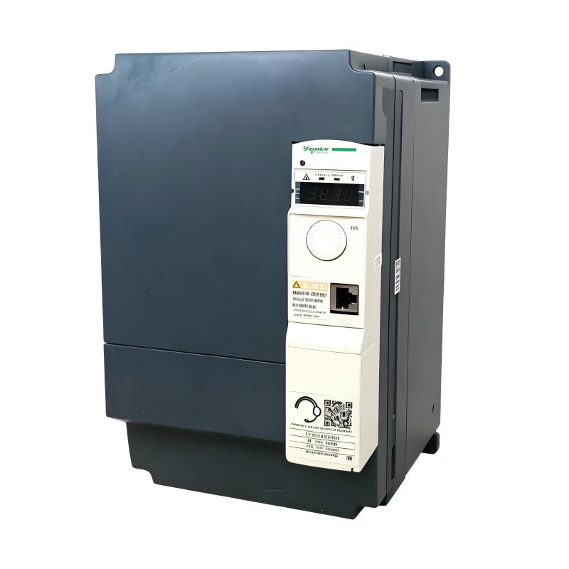
A critical finding in one LNG system showed relay chatter at ~5 Hz frequency, directly correlated with nearby VFD switching cycles.
3. Backplane and Mechanical Stability Inspection
- Inspect card seating depth
- Check for vibration-induced micro-movement
- Clean oxidized connector fingers
A 0.25 mm seating deviation was found to cause intermittent fault switching in a multi-channel rack.
4. EMI and Ground Loop Analysis
- Relay coils highly sensitive to EMI
- Shared grounding between high-power and safety circuits causes false triggering
After isolating grounding in one offshore platform, relay instability dropped by over 90%.
Common Field Failure Modes
Relay Contact Chatter (Most Frequent)
- Symptoms: rapid alarm toggling
- Cause: EMI or unstable supply
- Fix: grounding separation and cable rerouting
Backplane Contact Degradation
- Symptoms: intermittent channel faults
- Cause: oxidation or vibration wear
- Fix: cleaning or replacement
Power Supply Ripple Impact
- Symptoms: unstable relay activation
- Cause: shared DC bus load
- Fix: PSU isolation or filtering
Field Recovery Case Study
Case: False A2 Alarm Across Multiple Channels
Symptoms:
- Random A2 alarms during compressor operation
- No actual gas concentration change
Diagnosis:
- Sensor loop stable at 12.4 mA
- Relay outputs unstable only during motor start
- Backplane vibration detected
Root Cause:
Mechanical loosening of 05701-A-0327 card + shared grounding loop
Fix:
- Reseated cards
- Tightened rack locking mechanism
- Rewired grounding separation
Result:
Relay chatter eliminated; system stabilized within ±1% operational variance.