Allen-Bradley 100S-C09EJ14C Safety Contactor Installation Guide for Safety Motor Control Systems
Allen-Bradley 100S-C09EJ14C safety contactor installation issues are typically caused by incorrect coil voltage control, miswired auxiliary feedback contacts, or undervalued inrush current design, rather than mechanical failure of the contactor itself. In safety-rated motor control systems, this 9A contactor plays a critical role in ensuring forced-guided contact switching and safe torque off (STO)-level power isolation behavior.
Allen-Bradley 100S-C09EJ14C Role in Safety Control Architecture
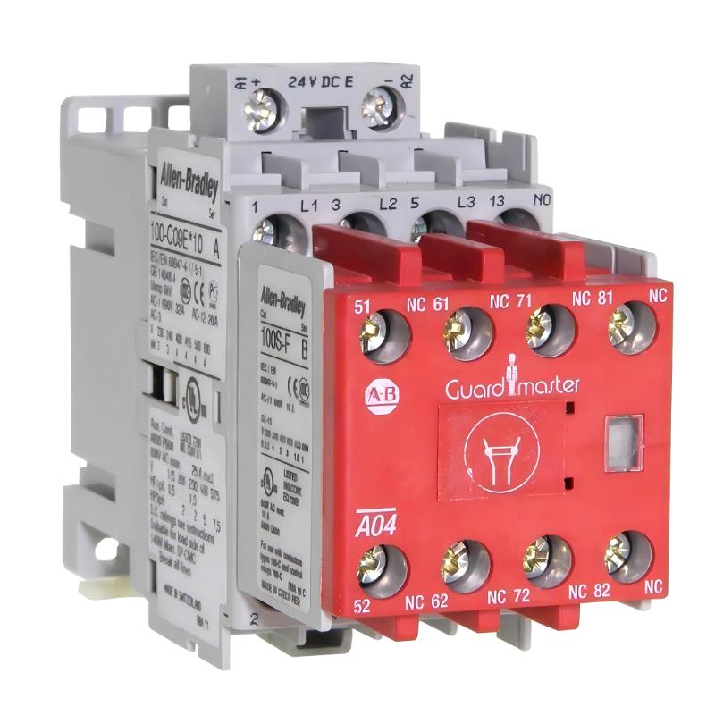
The Allen-Bradley 100S-C09EJ14C is a 9A IEC safety contactor with electrically controlled 24V DC coil, designed for safety circuits requiring reliable feedback and mechanically linked contacts.
Key functional roles:
- Safety-rated power isolation for motors and loads
- Integration with safety relays or safety PLC outputs
- Feedback loop monitoring via mirror contacts
- Control of E-Stop, guard door, and interlock circuits
Contact configuration (field-relevant):
- 3 NO main power poles
- 1 NO + 4 NC auxiliary/feedback contacts
In one packaging line upgrade, an incorrect assumption that NC feedback was “optional” caused the safety PLC to never detect contactor state change, resulting in a persistent safety fault even though the contactor was physically operating correctly.
Installation Conditions (Critical Engineering Checks)
Electrical Preconditions
- Coil supply strictly 24V DC stable (±10%)
- Inrush current capability verified for safety relay output
- Suppression diode or RC snubber installed on coil terminals
- No shared 24V rail with high inductive loads (solenoids, VFD brake circuits)
Field observation shows that coil undervoltage is the #1 cause of “chattering safety contactors”, especially during simultaneous machine startup.
Mechanical Preconditions
- DIN rail properly fixed with no vibration amplification
- Contactors aligned without mechanical stress on busbars
- Power terminal torque verified (loose terminals = heating risk)
- Adequate spacing between adjacent contactors for thermal dissipation
In a conveyor system case, repeated contactor dropout was traced to cabinet vibration causing micro-movement of DIN rail locks.
Wiring Logic (Safety-Critical Section)
Coil Control Circuit
- A1/A2 must be driven by safety relay or safety PLC output
- Avoid direct PLC output driving large coil loads
- Use interposing relay if output current is marginal
Power Circuit
- L1/L2/L3 → motor load or safety isolation path
- Ensure correct phase sequencing for motor applications
- Use short, low-resistance busbar connections
Feedback Circuit
- NC mirror contacts must be wired into safety monitoring loop
- PLC must verify contactor OFF-state integrity before restart
Field case: A machine failed safety validation because NC feedback was not wired, causing the safety PLC to assume contactor failure even though the system was mechanically healthy.
Commissioning Strategy (Field Engineering Practice)
Step 1: Coil Energization Test
- Apply 24V DC to coil under no load
- Verify full mechanical pull-in (no weak engagement)
- Measure coil voltage drop during activation
Observation: Coil dropped from 24V → 19.6V in one case due to undersized safety relay output.
Step 2: Safety Loop Verification
- Trigger E-Stop condition
- Confirm immediate contact opening (<50 ms typical)
- Validate feedback contact state change
Step 3: Load Stress Test
- Start motor under full load
- Monitor contactor temperature rise
- Observe coil stability during voltage dips
In one pump station, contactor dropout occurred only during simultaneous compressor start due to shared DC supply instability.