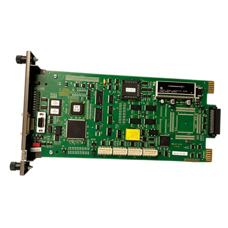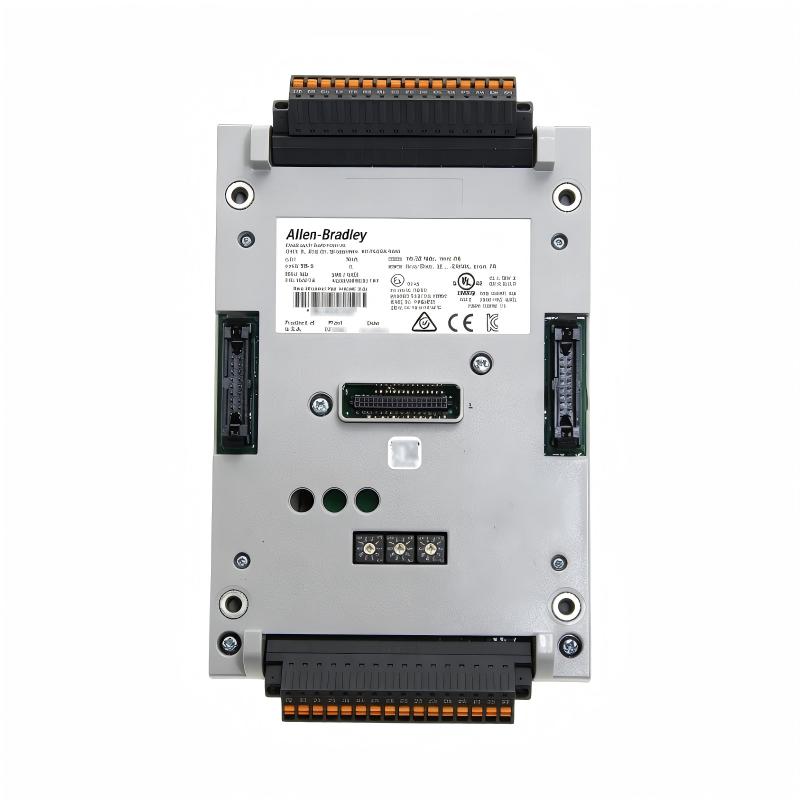
Allen-Bradley 1444-TB-A Dynamic Measurement Terminal Base Troubleshooting Guide (Fault Diagnosis)
Allen-Bradley 1444-TB-A dynamic measurement terminal base faults are commonly caused by loose sensor connections, incorrect shielding, wiring mistakes, grounding problems, or module interface issues rather than terminal base hardware damage. Troubleshooting requires analyzing the complete vibration measurement signal path.
This article describes a field case where an industrial motor monitoring system generated abnormal vibration alarms after maintenance work.
Allen-Bradley 1444-TB-A Dynamic Measurement Fault Symptoms
Typical fault symptoms include:
- False vibration alarms
- Sudden signal spikes
- Loss of sensor measurement
- Unstable trend data
- Incorrect machine condition evaluation
Field case:
A large process motor showed abnormal vibration values immediately after a scheduled cabinet inspection.
Initial observations:
- Motor mechanical condition: Normal
- Monitoring communication: Normal
- Vibration value: Intermittent spikes
The maintenance team suspected:
- Sensor damage
- Measurement module failure
- Mechanical vibration increase
Engineers started troubleshooting from the signal path.
Allen-Bradley 1444-TB-A Fault Diagnosis Process and Signal Analysis
Diagnostic path:
id="diag1444"Vibration Sensor||1444-TB-A Terminal Base||Dynamic Measurement Module||Monitoring Controller
Engineers checked:
- Sensor output
- Terminal connections
- Module diagnostics
- Historical vibration trends
Diagnostic results:
- Sensor output: Normal
- Module status: Normal
- Signal quality: Unstable
The fault location was narrowed to the connection interface.
Allen-Bradley 1444-TB-A Signal Interruption Investigation
Field measurements:
Before repair:
- Sensor output: Stable waveform
- Monitoring input: Random spikes
- Vibration alarm: Triggered repeatedly
Engineers inspected:
- Terminal screws
- Cable shielding
- Ground connection
- Terminal base seating
The investigation found:
- Shield wire termination was loose
- Electrical noise entered the measurement circuit
The terminal base was functioning, but the connection quality affected measurement accuracy.
Allen-Bradley 1444-TB-A Root Cause Analysis and Recovery
The final root cause was improper signal grounding.
Original condition:
- Sensor operated correctly
- Monitoring system stable
Failure condition:
- Shield connection degraded
- Noise affected measurement signal
- False vibration alarms appeared
Engineering conclusion:
The problem was caused by field wiring conditions, not terminal base failure.
Allen-Bradley 1444-TB-A Troubleshooting Repair and System Recovery
Corrective actions:
Signal Wiring Correction
Performed:
- Reconnected shield grounding
- Tightened terminals
- Verified sensor wiring
Measurement Verification
Tested:
- Vibration waveform
- Signal stability
- Alarm response
Final results:
Before repair:
- False alarms occurred frequently
- Operators questioned machine condition
After repair:
- Stable vibration monitoring
- Correct alarm behavior
- Reliable condition analysis restored
Allen-Bradley 1444-TB-A Common Fault Patterns and Diagnostic Methods
Unstable Vibration Signal Fault
Symptoms:
- Measurement value changes rapidly
Diagnosis:
- Check sensor wiring
- Inspect shielding
- Verify terminal connection
Signal Loss Fault
Symptoms:
- Monitoring channel shows no data
Diagnosis:
- Confirm terminal seating
- Check sensor power supply
- Verify module connection
False Alarm Fault
Symptoms:
- Machine alarm without mechanical issue
Diagnosis:
- Review signal noise
- Check grounding
- Compare sensor output with module reading
Allen-Bradley 1444-TB-A Long-Term Maintenance Strategy
For reliable dynamic measurement operation:
- Inspect terminal connections regularly
- Maintain proper cable shielding
- Record baseline vibration values
- Check sensor wiring during maintenance
- Keep monitoring documentation updated
A practical engineering rule:
“When troubleshooting an Allen-Bradley 1444-TB-A dynamic measurement terminal base problem, verify the sensor signal path before replacing hardware.”
Recommended troubleshooting sequence:
Sensor inspection → Terminal base check → Signal measurement → Grounding verification → Module diagnostics → Final monitoring test.