Triconex 4000103-510 Cable Assembly Installation Guide for Tricon Safety System
Triconex 4000103-510 cable assembly installation issues are rarely caused by the cable itself. In real field commissioning, most problems come from incorrect termination mapping, shielding grounding mistakes, or mismatch between I/O baseplate and termination panels. This cable is widely used in Tricon Safety Instrumented Systems (SIS), especially in TMR architecture output signal distribution.
Triconex 4000103-510 Cable Assembly Role in Tricon PLC System
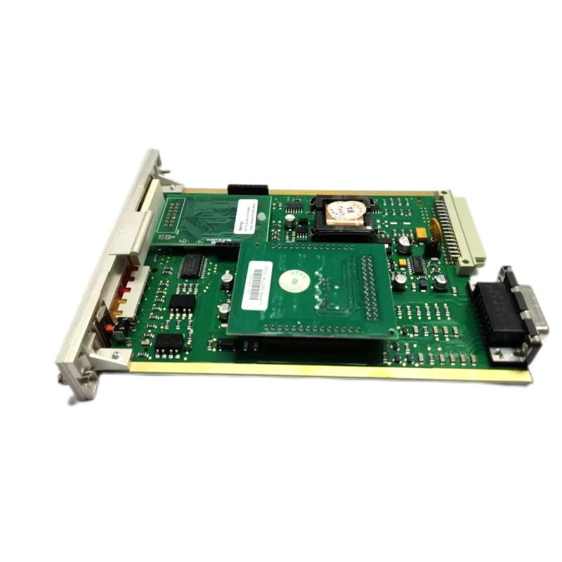
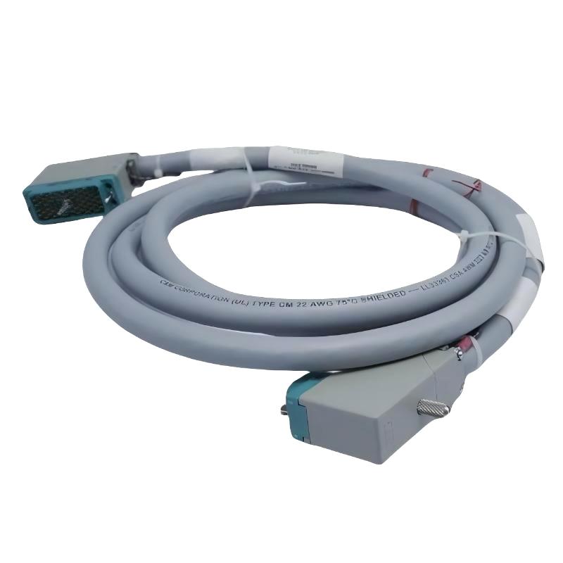
In a Triconex PLC controller architecture, the 4000103-510 cable assembly functions as the physical signal bridge between output modules and field termination panels.
It carries discrete control signals in a shielded multi-core design, ensuring redundant signal integrity in Triple Modular Redundant (TMR) systems.
In one refinery project, replacing manual wiring with this cable assembly reduced wiring errors by nearly 40%, mainly due to standardized pin mapping between modules and termination panels.
Triconex 4000103-510 Installation Preparation Checklist
Before Installation Guide execution, field engineers should verify the following:
- Shield grounding resistance below 1Ω
- Connector pin alignment on both ends
- No excessive bending stress (avoid tight routing near cabinet edges)
- Correct Tricon I/O module revision compatibility
In one gas compression station commissioning case, intermittent output instability was traced to an ungrounded shield drain wire, which introduced noise into adjacent 24VDC signal lines.
Triconex 4000103-510 Wiring and System Configuration
Correct wiring is critical for stable PLC Controller performance.
Key engineering rules:
- Maintain strict channel-to-channel mapping consistency
- Use single-point grounding for cable shield
- Avoid mixing signal return paths with power commons
- Confirm termination panel compatibility before energizing system
In one field case, swapped output channels caused incorrect valve activation during system dry testing, even though PLC logic was fully correct.
Triconex 4000103-510 Commissioning and Signal Validation
During Setup and Commissioning, engineers should:
- Verify stable 24VDC output under load conditions
- Check response time of output channels (typically <10 ms)
- Perform forced output testing from engineering workstation
In one startup scenario, signal noise appeared during VFD operation nearby. After rerouting the cable and improving grounding, signal stability was fully restored.
Field Engineering Insight
From real industrial experience, Triconex 4000103-510 installation issues are usually not hardware failures. They are system-level wiring or grounding problems.
Proper installation ensures:
- Stable PLC Controller output behavior
- Reduced EMI interference
- Reliable Safety Instrumented System performance