Honeywell 05701-A-0328 Single-Channel Control Card Installation Guide for DCS and Gas Detection Systems
Honeywell 05701-A-0328 single-channel control card installation errors are primarily caused by improper slot seating, unstable backplane voltage, or grounding issues, rather than internal electronic failure. In industrial DCS and System 57 gas detection racks, even a small misalignment can result in intermittent analog signal errors, false alarms, or PID loop instability.
Honeywell 05701-A-0328 Control Card Role in System 57 and DCS Architecture
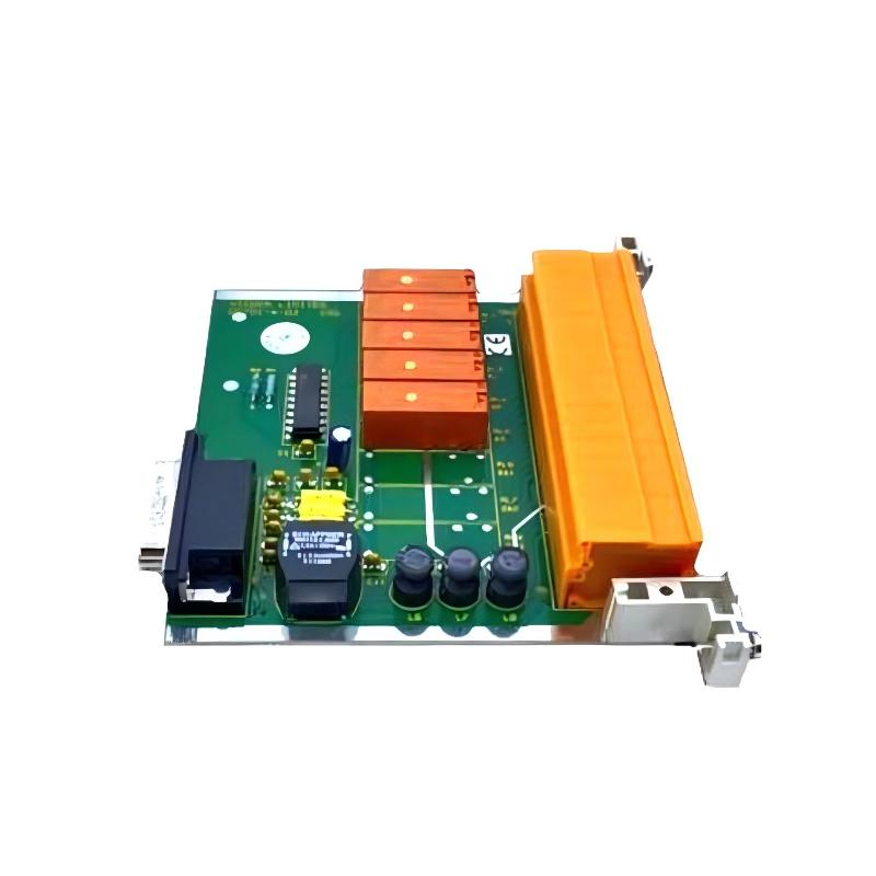
The 05701-A-0328 card is designed for single-channel analog or digital process control. It is commonly used in Honeywell Experion PKS, System 57, and legacy TDC racks. Its main responsibilities include:
- Processing a single 4–20 mA analog input
- Performing PID control or ON/OFF control for one loop
- Evaluating alarm thresholds (A1, A2, A3)
- Communicating with redundant controller modules
- Displaying card status through front-panel LEDs (Power, Fault, Inhibit)
In one chemical plant installation, operators reported repeated false A2 alarms. Field inspection showed the 05701-A-0328 card was slightly tilted, causing sporadic analog input misreads. Re-seating corrected the problem immediately.
Honeywell 05701-A-0328 Installation Preparation
Before installing the card, engineers should ensure:
- Power to the system rack is turned off.
- Backplane connectors are clean and free from oxidation.
- Rack slots are mechanically intact and aligned.
- Ambient temperature is within operational range (0–60°C).
In a refinery, oxidation on the backplane increased noise by ~12%, causing intermittent “Fault” LED activation until contacts were cleaned.
Mechanical Installation and Electrical Integration
Mechanical Procedure
- Align the card carefully with the slot guide rails
- Push until the latch clicks to secure the card
- Verify no tilt or partial seating
- Tighten front-panel retention screws to prevent vibration loosening
Electrical Considerations
- Ensure 24 V DC supply is stable
- Properly ground the chassis
- Keep analog signal cables away from high-power AC lines to reduce EMI
In a gas processing facility, EMI from nearby VFDs caused unstable PID output. After rerouting analog cables and adding grounding straps, signal noise dropped from ±18 mV to ±2 mV.
Honeywell 05701-A-0328 Commissioning Strategy
Cold Start Verification
- Confirm Power, Fault, and Inhibit LEDs operate correctly
- Measure baseline 4–20 mA input for stability
Dynamic Signal Testing
- Inject test signals to verify PID output
- Check alarm threshold response timing (<1 second typical)
Full System Stress Test
- Activate all channels in the rack simultaneously
- Monitor signals under thermal and mechanical load
- Verify no cross-channel interference
In one offshore compressor station, voltage drift occurred only with multiple active channels due to shared grounding paths. After isolating the grounds, signals stabilized to ±1% deviation.