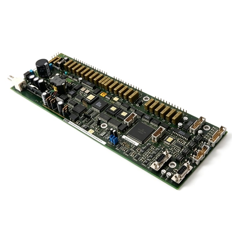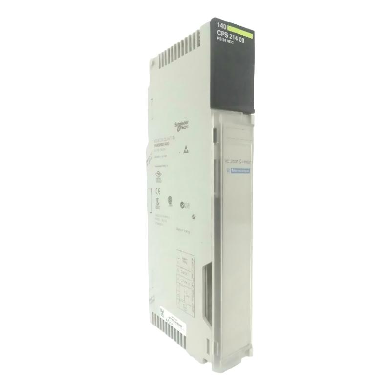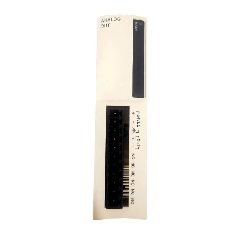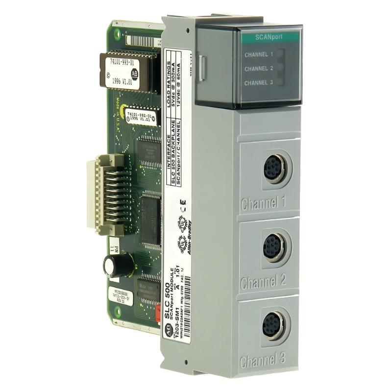
Allen-Bradley 1203-SM1 SLC to SCANport Communication Module Installation Guide (Setup & Commissioning)
Allen-Bradley 1203-SM1 SLC to SCANport Communication Module installation problems are usually caused by incorrect rack configuration, SCANport cable issues, or improper communication setup rather than a defective module. During field commissioning, engineers often find that the hardware is functional but the SLC processor cannot exchange valid data because the module channel configuration or drive communication parameters are incorrect.
The Allen-Bradley 1203-SM1 communication module provides an interface between an SLC processor and SCANport-compatible devices such as AC drives. It allows SLC systems to control and monitor multiple SCANport devices through structured I/O data exchange and messaging functions.
Allen-Bradley 1203-SM1 Communication Module Installation Overview and System Role
The 1203-SM1 is typically installed in an Allen-Bradley SLC rack to bridge legacy PLC control logic with SCANport devices.
Typical applications include:
- Motor speed control
- Drive start/stop commands
- Drive status monitoring
- Parameter read/write operations
A common field application involved an SLC 5/04 controller controlling three Allen-Bradley 1336 PLUS AC Drive units through a single 1203-SM1 module.
During initial startup:
- PLC RUN status: normal
- Module power LED: normal
- Drive communication: unstable
The initial assumption was module failure. However, signal tracing showed that the SCANport network topology was incorrect.
After correcting cable routing and channel assignment, communication recovery was immediate.
Allen-Bradley 1203-SM1 Installation Preparation and Hardware Inspection
Before installing the PLC communication module, engineers should verify:
- SLC rack compatibility
- Available slot position
- SCANport cable condition
- DIP switch settings
- Enclosure depth and wiring space
The manufacturer documentation highlights that the SLC rack containing a 1203-SM1 requires sufficient enclosure depth, and installation planning should include SCANport cable placement before powering the system.
A practical field checklist:
| Inspection Item | Engineering Check |
|---|---|
| Rack power supply | Stable 24V DC / backplane supply |
| Module seating | Fully inserted into SLC slot |
| Cable length | Within SCANport limits |
| Grounding | Shield connected correctly |
| Drive address | Matches PLC logic |
Allen-Bradley 1203-SM1 SCANport Wiring and Network Configuration
The SCANport communication connection is the most common installation failure point.
Recommended practice:
- Keep SCANport cables away from motor power cables
- Avoid sharp cable bending
- Check connector locking condition
- Verify channel assignment
In one conveyor system commissioning case:
Initial condition:
- Channel 1 drive: online
- Channel 2 drive: intermittent
- Channel 3 drive: offline
Measured conditions:
- Cable shield continuity: OK
- Communication voltage: unstable
- Cable routing distance near VFD output cable: 15 meters
After separating communication wiring from power conductors:
- Communication error count dropped from 86/hour to zero
- PLC status data became stable
The problem was electromagnetic interference, not the 1203-SM1 module.
Allen-Bradley 1203-SM1 PLC Communication Setup and Configuration
The commissioning engineer must configure both the SLC program and SCANport device parameters.
Important configuration areas:
- Input/output data mapping
- Basic Mode or Enhanced Mode selection
- Channel enable bits
- Drive parameter access logic
The 1203-SM1 supports communication functions including direct logic transfer and enhanced messaging features depending on the SLC controller type.
Typical diagnostic logic:
IF Module_Status = Healthy
AND Channel_Enable = TRUE
AND Drive_Status = Ready
THEN
Allow Start Command
This simple logic prevents unnecessary drive commands during communication loss.
Allen-Bradley 1203-SM1 Commissioning Validation and Performance Testing
A successful setup requires more than seeing the module online.
Commissioning tests should include:
Communication Test
Verify:
- PLC command changes
- Drive response
- Status feedback
Dynamic Motor Test
Observe:
- Acceleration response
- Current stability
- Fault feedback
Example commissioning data:
Before correction:
- Drive response delay: 2.8 seconds
- Communication retries: 40/min
After configuration adjustment:
- Response delay: <200 ms
- Communication retries: 0
Field experience shows that most 1203-SM1 installation issues are discovered through communication behavior analysis rather than visual inspection.