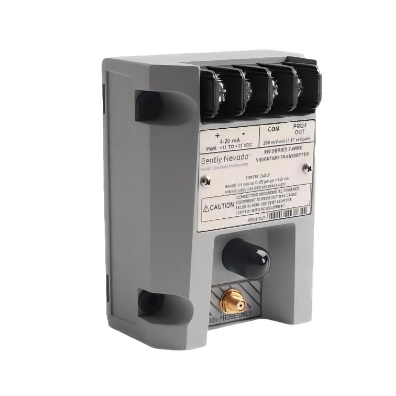
Bently Nevada 990-04-70-02-05 Vibration Transmitter Installation Guide (990 Series Loop-Powered Sensor Setup & Commissioning)
Bently Nevada 990-04-70-02-05 vibration transmitter installation problems are typically caused by incorrect probe system matching, loop power instability, or improper mounting alignment, rather than transmitter internal failure. In real rotating equipment monitoring applications such as compressors and small turbine skids, most “signal drift” issues are traced back to 3300 NSv probe gap setting errors or wiring noise in the 4–20 mA loop.
Bently Nevada 990-04-70-02-05 Role in Machinery Monitoring System
The Bently Nevada 990-04-70-02-05 is a 2-wire loop-powered vibration transmitter used in continuous monitoring of rotating machinery such as:
- Pumps
- Small compressors
- Motors and fans
- OEM packaged skids
It converts the proximity probe signal into a 4–20 mA vibration output, which is then fed into PLC, DCS, or protection systems.
In one field retrofit case on a centrifugal compressor skid, the transmitter was integrated directly into a PLC analog input card for condition monitoring, replacing an older discrete vibration switch system.
Bently Nevada 990-04-70-02-05 Installation Preparation (Field Reality)
Before installation, engineers typically verify the following critical conditions:
- Correct pairing with 3300 NSv proximity probe system
- System length selection (commonly 7.0 m version for 990-04-70-02-05)
- Stable 24 VDC loop power supply (12–35 VDC allowable range)
- Shield grounding strategy (single-point grounding recommended)
- Mechanical probe mounting rigidity
In one commissioning case, a pump skid showed unstable vibration readings simply because the probe cable shield was grounded at both ends, creating a low-frequency noise loop.
Bently Nevada 990-04-70-02-05 Wiring & Setup Procedure (Practical Engineering Method)
Unlike simple transmitters, the 990 system requires correct signal chain alignment:
Probe → Extension Cable → Transmitter → 4–20 mA Loop
Field installation steps typically include:
- Verify probe gap voltage within stable linear region
- Connect coaxial sensor cable to transmitter input
- Ensure loop polarity correctness (+ / - terminals)
- Confirm 250 Ω loop load compatibility if used in test setup
- Secure cable routing away from VFD and motor power lines
In one gas compressor application, incorrect polarity wiring caused the output to saturate at 4 mA, misleading operators into thinking the machine was running in “zero vibration” condition.
Bently Nevada 990-04-70-02-05 Commissioning Behavior & Signal Validation
During startup, a healthy system should show:
- Stable 4–20 mA proportional vibration signal
- No rapid drift during constant speed operation
- Smooth response during load changes
Field observation example:
- Initial condition: vibration signal fluctuating between 6–14 mA under steady load
- Mechanical inspection: no rotor issues detected
- Root cause: loose probe extension cable connector causing micro-intermittent signal loss
- After tightening connector: stable 9.2 mA baseline achieved and held for 48 hours
This type of failure is commonly misdiagnosed as bearing wear, while the actual issue is signal chain instability.