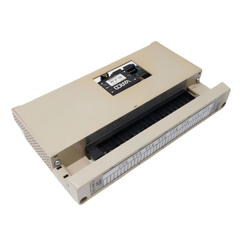
ABB 59012720 DDCS/ISA Adapter Module Card Installation Guide for ABB Drive Communication Systems
ABB 59012720 DDCS/ISA adapter module installation issues are most commonly caused by incorrect DDCS optical link termination, adapter slot mismatch, or grounding imbalance in the drive cabinet, rather than failure of the module itself. In ABB DDCS (Distributed Drive Communication System) architectures, this adapter acts as a bridge between ISA-based control systems and ABB drive communication networks, so signal integrity is highly sensitive to installation quality.
ABB 59012720 DDCS/ISA Adapter Role in Drive Communication Architecture
The ABB 59012720 (often associated with NISA-03 DDCS/ISA adapter kit) is used to integrate:
- ISA-based control systems (legacy industrial automation platforms)
- ABB drives communication layer (DDCS optical fiber network)
- Central drive controllers (ACS600 / ACS800 families in legacy systems)
It functions as a protocol and physical interface converter, enabling ISA-level control commands to be transmitted through ABB’s DDCS fiber-optic communication system.
In one modernization project in a paper mill, a legacy ISA controller could not read drive status from multiple ACS600 units. The issue was resolved after installing the DDCS/ISA adapter, but initial commissioning failed due to reversed fiber polarity on the DDCS link.
ABB 59012720 Installation Preparation (Critical Preconditions)
Before installation, engineers must ensure both communication topology and optical integrity are verified.
Cabinet and System Conditions
- Drive cabinet properly grounded (single-point grounding preferred)
- No high-frequency noise sources near DDCS fiber routing
- Adequate separation between power cables and communication fibers
- Ambient temperature within -20°C to +70°C
Field experience shows that poor cabinet grounding often introduces communication jitter in DDCS diagnostics, especially during drive acceleration phases.
DDCS Fiber Link Preparation
DDCS uses fiber-optic communication at high speed (~4 Mbit/s):
- Blue connector: receiver side
- Grey connector: transmitter side
- Maximum typical distance: ~10 meters between nodes
- Fiber bending radius must not be violated (avoid sharp bends <25 mm)
In one steel plant, intermittent drive “communication loss” alarms were traced to excessive fiber bending behind the cabinet door. Re-routing restored stable communication.
ABB 59012720 Installation Procedure (Field Engineering Practice)
Unlike standard I/O modules, this adapter is sensitive to both mechanical seating and optical polarity correctness.
Mechanical Installation
- Mount adapter securely in designated drive communication slot
- Ensure full connector engagement (no partial seating allowed)
- Tighten fastening points to prevent vibration loosening
- Confirm no strain on fiber connectors after installation
Optical Connection Steps
- Connect DDCS fiber A → corresponding drive port
- Connect return fiber B → correct direction (avoid swap)
- Ensure clean optical ferrules (dust causes major signal loss)
- Verify no micro-bending at cabinet entry point
In one commissioning case, a simple fiber swap caused the entire drive network to disappear from the controller scan, even though all hardware was functional.
ABB 59012720 Commissioning Strategy (Drive Communication Validation)
Commissioning should focus on communication stability under dynamic load, not just initial connectivity.
Step 1: Static Link Verification
- Confirm DDCS node detection from ISA system
- Check module initialization status
- Validate LED indicators on adapter module
Step 2: Command Transmission Test
- Send basic start/stop commands
- Verify response time consistency across drives
- Check status word feedback (RUN, FAULT, READY)
Step 3: Dynamic Load Stress Test
- Run multiple drives simultaneously
- Monitor communication stability during acceleration
- Check for packet loss during load transitions
In a real field case at a petrochemical plant, communication errors appeared only when all pumps started simultaneously. Root cause was a marginal fiber connector loss of ~2 dB attenuation.