Allen Bradley 1606-XL240EP Power Supply Fault Diagnosis & Troubleshooting Guide (DC Drop, Restart Loop, No Output Failure)
Introduction
Allen Bradley 1606-XL240EP troubleshooting cases are frequently misdiagnosed as internal power supply failure. In real field systems, the majority of issues come from load transients, wiring resistance, or uneven DC distribution, not the PSU itself.
This is especially common in PLC Controller systems where solenoids, sensors, and communication modules share a single 24V rail.
Fault Symptoms in Real Industrial Applications
Typical symptoms include:
- PLC random restart or brownout
- 24VDC output instability under load
- DC OK relay flickering
- Power supply restart cycling
- Voltage stable at idle but collapsing during switching
In one conveyor system, PLC resets occurred every 20 minutes even though idle voltage readings were normal.
Engineering Diagnostic Thinking Process
Field engineers usually follow a structured logic:
- Is AC input stable during load switching?
- Does voltage drop occur only during transient events?
- Is load switching simultaneous or staggered?
- Is wiring resistance causing voltage loss?
Observation:
During solenoid activation, voltage dropped to 21.9V, triggering PLC undervoltage reset even though PSU output was nominal.
Case Study: Random PLC Restart in Packaging System
System Configuration:
- PLC: CompactLogix
- Loads: sensors + solenoid valves + communication module
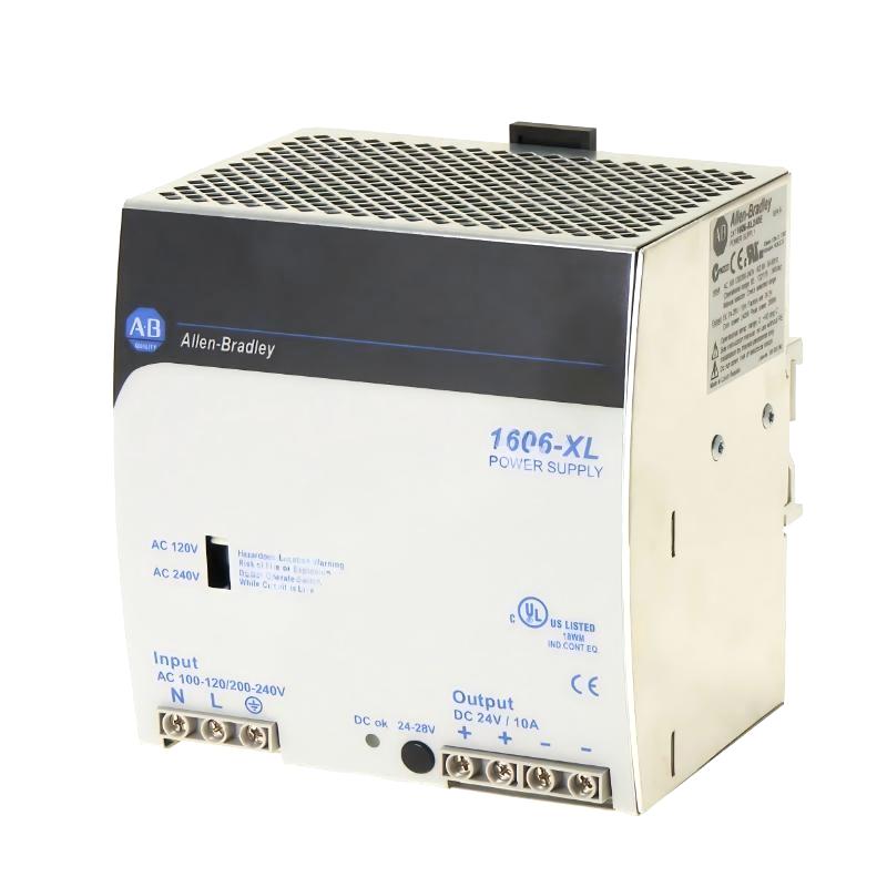
- Power supply: 1606-XL240EP
Symptoms:
- Random restart every 10–30 minutes
- DC OK signal unstable
- No internal fault alarms
Diagnosis Process:
Measurements showed:
- PSU output: stable at terminals
- PLC input voltage: fluctuating 22.0–24.1V
- Voltage drop increases during simultaneous solenoid activation
Root Cause:
- Long 24VDC cable run (~15–20 meters)
- Undersized wire gauge
- All loads sharing a single DC branch
- High inrush current from solenoid bank
Correction:
- Split DC loads into two branches
- Increased wire cross-section
- Staggered solenoid activation sequence
Result:
- Voltage drop reduced below 0.4V
- PLC reset issue completely eliminated
Common Fault Patterns
1. DC OK Relay Flicker
Usually caused by:
- transient voltage dips
- loose terminals
- high inrush current events
2. Output Voltage Collapse
Root causes:
- overloaded single DC rail
- long cable resistance
- simultaneous inductive switching
3. Thermal Instability
Observed when:
- cabinet temperature exceeds 45°C
- continuous operation near rated load
- poor ventilation around DIN rail
Repair Strategy (Field Method)
Step 1: Load Isolation Test
Disconnect all external loads:
- If stable → external system issue
- If unstable → PSU or AC input issue
Step 2: Voltage Drop Mapping
Measure at:
- PSU output
-
PLC input terminal
Difference greater than 1V indicates wiring problem
Step 3: Switching Load Analysis
Check solenoid and relay timing:
- If simultaneous switching occurs → stagger sequence required
Engineering Insight
In most field cases, the 1606-XL240EP is incorrectly blamed for failures. In reality, it is a stable industrial power supply, but highly sensitive to system-level DC design quality.
Final Conclusion
If instability occurs in a 1606-XL240EP system, the priority is:
- check load distribution first
- verify wiring resistance
- analyze switching behavior
- only then evaluate the power supply itself
Most issues are resolved without replacing the unit.