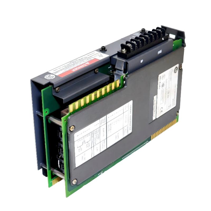
Allen-Bradley 1402-LS51 Line Synchronization Module Installation Guide (Wiring & Commissioning)
Allen-Bradley 1402-LS51 Line Synchronization Module installation problems are usually caused by incorrect voltage sensing connections, wrong phase sequence, inaccurate configuration parameters, or improper PLC integration rather than a defective synchronization module. In generator control applications, the module may communicate correctly with the PLC while still failing to achieve synchronization because the measured voltage, frequency, or phase angle values are incorrect.
The Allen-Bradley 1402-LS51 Line Synchronization Module is designed for electrical synchronization applications where two three-phase power sources must be monitored and matched before connection. It provides important measurement information including voltage difference, frequency difference, and phase relationship to help automation systems perform safe synchronization control.
Allen-Bradley 1402-LS51 Line Synchronization Module Application Overview
The 1402-LS51 operates as an electrical measurement and synchronization interface between a generator source and an existing power bus.
Typical system structure:
Generator Output
        |
        |
Voltage / Frequency Measurement
        |
        |
Allen-Bradley 1402-LS51 Module
        |
        |
PLC Controller System
        |
        |
Breaker Synchronization Control
Main functions:
- Monitor three-phase voltage conditions
- Detect frequency difference
- Measure phase angle difference
- Provide synchronization status information
- Support automatic generator connection control
Typical applications:
- Standby generator systems
- Industrial power plants
- Backup energy systems
- Cogeneration systems
- Factory power distribution networks
In one industrial power system commissioning project, engineers installed a 1402-LS51 module for automatic generator synchronization.
During startup testing:
- PLC communication: Normal
- Module status: Normal
- Generator breaker: Unable to close
The initial assumption was that the PLC synchronization logic was incorrect.
Engineers performed a field investigation:
- Checked voltage sensing wiring
- Verified phase sequence
- Compared measurement values
- Reviewed synchronization limits
Measured conditions:
Before correction:
- Bus voltage: 415 VAC
- Generator voltage: 412 VAC
- Frequency difference: 0.6 Hz
- Phase angle deviation: Above allowable range
Further inspection found that one voltage sensing channel had an incorrect phase connection.
After correction:
- Phase measurement became accurate
- Synchronization conditions were achieved
- Generator breaker closed successfully
The issue was caused by installation wiring rather than module failure.
Allen-Bradley 1402-LS51 Installation Preparation and Electrical System Planning
Before installing the Line Synchronization Module, engineers should understand the complete electrical synchronization system.
Preparation requirements:
- Confirm generator voltage rating
- Verify bus voltage conditions
- Review transformer wiring
- Prepare PLC configuration
- Check protection requirements
Installation checklist:
| Inspection Item | Engineering Requirement |
|---|---|
| Voltage input | Correct three-phase measurement |
| Phase sequence | Must match system design |
| PLC integration | Correct module configuration |
| Grounding | Proper electrical grounding |
| Control wiring | Correct signal assignment |
A common field mistake is treating the 1402-LS51 as a normal PLC expansion module.
Unlike standard digital or analog modules, synchronization equipment depends heavily on:
- Accurate electrical measurement
- Correct phase relationship
- Stable frequency calculation
- Proper control logic
Incorrect sensing wiring can create symptoms that appear to be module failure.
Allen-Bradley 1402-LS51 Line Synchronization Module Wiring Installation
Correct electrical wiring determines synchronization accuracy.
Voltage Measurement Wiring
Engineers should verify:
- Three-phase voltage input connection
- Correct phase identification
- Transformer polarity
- Voltage range compatibility
PLC Interface Connection
Check:
- Module installation position
- Communication status
- Data exchange configuration
Synchronization Control Wiring
Verify:
- Enable signals
- Status feedback
- Breaker control interface
In one commissioning case:
Initial condition:
- Generator started correctly
- Synchronization sequence initiated
- Breaker closing command rejected
Engineering measurements:
Before correction:
- Voltage difference: Within limit
- Frequency difference: Acceptable
- Phase angle: Incorrect
Investigation found:
- Phase B and Phase C sensing wires were reversed
After rewiring:
- Phase angle measurement returned normal
- Synchronization process completed successfully
Allen-Bradley 1402-LS51 Setup and System Configuration
The configuration stage determines whether the synchronization system operates correctly.
Important settings include:
- Voltage tolerance
- Frequency matching range
- Phase angle limit
- Synchronization timing
- PLC control conditions
Typical commissioning logic:
IF Voltage_Difference < Setting_Limit
AND Frequency_Error < Setting_Limit
AND Phase_Angle < Allowed_Value

THEN

Enable Synchronization Command
Engineers should verify:
- Measurement values are realistic
- Synchronization status changes correctly
- PLC receives valid data
- Breaker control sequence works properly
Field experience shows that incorrect configuration values often create false synchronization failures.
Allen-Bradley 1402-LS51 Commissioning Validation and Performance Testing
Final commissioning should simulate actual operating conditions.
Electrical Measurement Test
Check:
- Voltage readings
- Frequency values
- Phase angle calculation
Synchronization Operation Test
Verify:
- Generator startup
- Voltage matching
- Frequency matching
- Breaker closing sequence
Example commissioning results:
Before optimization:
- Synchronization attempts failed
- Phase error: 8 degrees
- Generator connection unavailable
After correction:
- Phase matching stable
- Synchronization completed
- Generator operation verified
A successful Allen-Bradley 1402-LS51 installation requires accurate electrical wiring, correct system configuration, and practical field commissioning.