Allen-Bradley 1203-GU6 Enhanced DeviceNet Communication Module Installation Guide for SCANport Drive Integration
Allen-Bradley 1203-GU6 Enhanced DeviceNet communication module installation issues are typically caused by SCANport cable shielding problems, DeviceNet node address conflicts, or unstable 24V DC supply on the communication adapter, rather than module hardware failure. This module functions as a protocol gateway between SCANport drives and DeviceNet networks, enabling PLC-level access to drive parameters, diagnostics, and control functions.
Allen-Bradley 1203-GU6 Role in DeviceNet / SCANport Architecture
The 1203-GU6 is an Enhanced DeviceNet communications adapter used to integrate SCANport-compatible drives into industrial DeviceNet networks.
It provides:
- SCANport-to-DeviceNet protocol conversion
- Drive parameter read/write capability
- Fault diagnostics and status monitoring
- Single-drive communication per module
- Support for 1336, 1305, and SCANport-based drives
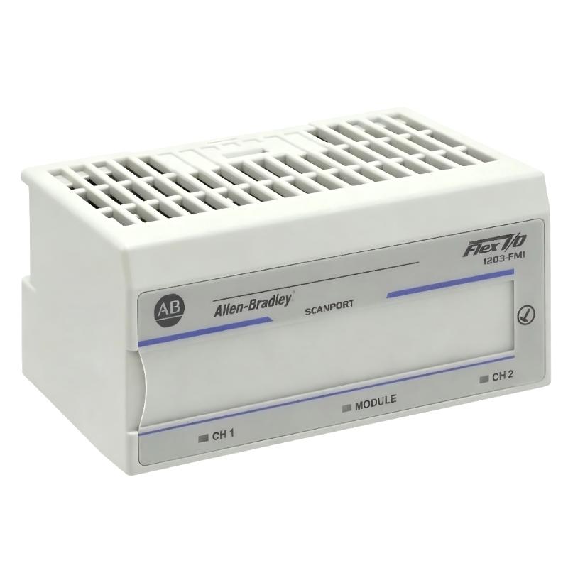
According to Rockwell documentation, the module is mounted on DIN rail and connects via:
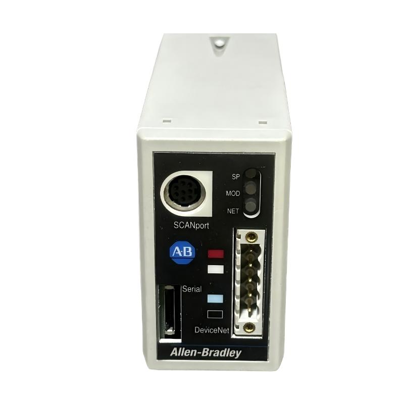
- 8-pin SCANport mini-DIN cable
- 5-pin or 10-pin DeviceNet connector interface
In field modernization projects, this module is often used to retrofit legacy SCANport drives into newer PLC-controlled DeviceNet systems without replacing the drive hardware.
Installation Conditions (Critical Engineering Requirements)
1. Electrical Power Stability
- 24V DC DeviceNet supply must remain stable under load
- Voltage dips during motor start must be avoided
- Separate power supply recommended from VFD control circuits
Field observation shows that even short voltage dips can cause:
- DeviceNet node dropout
- SCANport communication reset
- Drive parameter read failure
2. DeviceNet Network Integrity
- Each 1203-GU6 must have a unique node address (MAC ID equivalent)
- Correct baud rate (125k / 250k / 500k) must match network
- Proper termination resistors at both ends of trunk line
- CAN_H / CAN_L polarity must be verified before energizing
A single reversed CAN wire can bring down the entire network segment.
3. SCANport Cable Conditions (Critical Failure Point)
- Use only approved SCANport cable
- Maintain shielding continuity
- Avoid routing near inverter output cables
- Keep cable length within recommended limits (<10 m typical)
Field case: intermittent drive “offline” status was traced to SCANport cable running parallel to VFD output, causing EMI coupling.
Installation Procedure (Field Engineering Practice)
Step 1: DIN Rail Mounting
- Mount module securely on 35 mm DIN rail
- Ensure proper grounding via DIN rail contact
- Avoid vibration-prone cabinet zones
Step 2: DeviceNet Wiring
- Connect 5-pin DeviceNet connector
- Verify V+, V-, CAN_H, CAN_L, Shield continuity
- Confirm termination resistors installed at both network ends
Step 3: SCANport Connection
- Connect SCANport cable to drive
- Ensure full locking of mini-DIN connector
- Verify drive is powered before communication test
Step 4: Node Configuration
- Set unique node address (default often 63)
- Ensure no duplicate nodes in scan list
- Verify module appears in PLC scanner or RSNetWorx
Commissioning Strategy (Engineering Logic)
Step 1: Power-Up Validation
- Confirm module LED status stable
- Verify DeviceNet network scan completion
- Ensure SCANport device recognized correctly
Step 2: Parameter Communication Test
- Read drive speed reference
- Retrieve fault codes
- Confirm parameter read/write capability
Step 3: Load Condition Test
- Run motor under light load
- Observe communication stability during acceleration
- Check for node dropout during inrush current
In one steel plant case, communication instability only occurred during conveyor startup due to EMI coupling into SCANport wiring.