Emerson 12P0631X012 DeltaV Cable Installation Guide for DeltaV DCS Communication Systems
Emerson 12P0631X012 DeltaV cable installation issues are usually caused by incorrect DB25 connector pin alignment, signal bus extender misrouting, or shielding discontinuity, rather than cable material failure. In DeltaV distributed control systems, this cable functions as a parallel cord bus extender, and any signal degradation can directly impact controller-to-module communication stability.
Emerson 12P0631X012 Role in DeltaV System Architecture
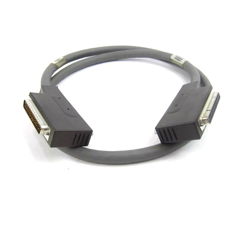
The Emerson 12P0631X012 is a DeltaV parallel bus extender cable used to extend communication between DeltaV system modules and control hardware.
Core functions:
- Extends DeltaV parallel communication bus distance
- Maintains signal integrity between controller and I/O modules
- Supports DB25-to-DB25 interconnection architecture
- Used in DeltaV rack-to-rack or module extension scenarios
According to field data and distributor specifications, it is commonly used as a short-range high-integrity bus extender cable for DeltaV DCS systems, typically around 0.25m–10ft depending on configuration.
In one refinery modernization case, intermittent module communication failure was traced to a partially loosened DB25 connector on this cable, not the controller itself.
Installation Conditions (Critical Engineering Requirements)
1. Mechanical Connection Integrity
- DB25 connectors must be fully seated and locked
- No side load or mechanical stress on cable ends
- Avoid sharp bending near connector heads
- Ensure rack alignment before tightening
Field observation shows that even a 1–2 mm connector offset can cause intermittent bus errors under vibration conditions.
2. Electrical Signal Integrity
- Maintain proper shielding continuity across both ends
- Avoid running cable near VFD output or high-current motor lines
- Ensure grounding strategy follows single-point grounding rule
- Do not mix with analog signal cables
In one chemical plant, signal instability was caused by routing the DeltaV cable parallel to inverter output cables, inducing noise into the communication path.
3. System Power Stability Dependency
Although this is a passive cable, system stability depends on:
- Stable DeltaV controller power supply
- No voltage dips during load transitions
- Proper grounding of control cabinet
Field cases show communication dropouts often coincide with motor start events due to shared grounding instability.
Installation Procedure (Field Engineering Practice)
Step 1: Physical Routing
- Route cable away from high-noise electrical equipment
- Maintain minimum bend radius to avoid internal conductor stress
- Secure cable with clamps to prevent vibration movement
Step 2: Connector Installation
- Align DB25 male/female connectors precisely
- Push until full engagement is confirmed
- Tighten screws evenly on both sides
- Verify no pin bending or partial insertion
Step 3: System Verification
- Power up DeltaV controller system
- Check module recognition in system diagnostics
- Monitor communication status tags
- Confirm no intermittent “module offline” events
Commissioning Strategy (Engineering Logic)
Step 1: Static Communication Check
- Verify all connected modules detected
- Confirm no bus initialization errors
- Check system event logs for communication warnings
Step 2: Load Transition Test
- Run system under normal process load
- Observe communication stability during pump/motor startup
- Monitor for transient signal loss or retries
Step 3: Long-Duration Stability Test
- Run system continuously under process conditions
- Check for periodic communication degradation
- Validate shielding effectiveness in real operating conditions
In one LNG facility, instability only appeared during peak compressor load, later traced to poor shielding continuity on a single DB25 connector.