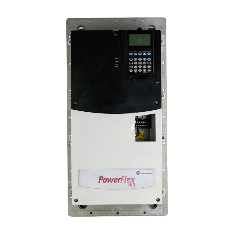
Allen Bradley 20AD065A0AYNANC0 PowerFlex 70 AC Drive Troubleshooting Guide (Fault Diagnosis & Repair)
Diagnosing Problems with the Allen Bradley 20AD065A0AYNANC0
The Allen Bradley 20AD065A0AYNANC0 PowerFlex 70 AC drive regulates motor speed and operation in industrial machinery. When the motor stops unexpectedly, accelerates too slowly, or produces an unstable speed response, the cause may involve the power supply, motor circuit, drive parameters, control signals, or mechanical load.
Troubleshooting should begin with the drive's displayed fault information and operating history. Record the fault code, motor current, output frequency, and machine conditions before resetting the drive.
A fault that repeatedly returns after a reset should be investigated rather than treated as an isolated event.
2. PowerFlex 70 Troubleshooting: Motor Fails to Start
When the drive powers up but the motor does not run, first determine whether the drive is receiving a valid start command.
Follow this diagnostic sequence:
Check the drive display for active faults or alarms.
Confirm that the drive is ready for operation.
Monitor the start command from the PLC or control terminals.
Verify the selected command source.
Check the configured speed reference.
Inspect external interlocks and permissive conditions.
Confirm that the motor circuit is correctly connected.
If the drive receives a start command but remains stopped, examine the control configuration before suspecting an internal power-stage failure.
Also check whether the reference value is below the configured minimum frequency or whether a programmed stop condition is preventing operation.
3. Overcurrent Fault Diagnosis on the PowerFlex 70
An overcurrent fault indicates that the drive has detected excessive current during operation. Possible causes include a motor or cable fault, excessive mechanical load, unsuitable acceleration settings, or incorrect motor configuration.
Begin by checking:
Motor cable insulation and terminal condition.
Motor winding condition.
Mechanical obstruction or excessive load.
Motor nameplate data entered into the drive.
Acceleration and deceleration settings.
Motor connection and grounding.
Operating current under normal load.
If an insulation test is required, disconnect the motor cable from the drive before testing the motor circuit. Applying an insulation tester to connected drive output terminals can damage the electronic components.
Do not repeatedly reset an overcurrent fault without checking the motor and connected equipment.
4. Troubleshooting DC Bus Overvoltage During Deceleration
A DC bus overvoltage fault may occur when the motor returns energy to the drive during deceleration. This condition is more likely in applications involving high-inertia loads or frequent stopping cycles.
Potential causes include:
Deceleration time set too short.
High rotational inertia.
Rapid changes in load conditions.
Unsuitable braking configuration.
Incoming supply voltage outside the permitted range.
Faults in an installed braking circuit.
Check the deceleration profile against the machine's actual stopping requirements. A longer deceleration time may reduce regenerative energy. If the application requires rapid stopping, confirm that the drive's braking arrangement is correctly selected and installed.
Any braking resistor or associated component must be checked against the drive's specific configuration and manufacturer's requirements.
5. PowerFlex 70 Speed Reference and Control Signal Faults
Incorrect speed response can be caused by problems with the reference signal rather than the drive's motor output stage.
For analog-controlled applications, inspect the reference wiring, signal common, shielding, and scaling configuration. For PLC-controlled applications, check the communication data and the selected reference source.
A useful diagnostic approach is to compare three values:
The speed reference generated by the PLC or control device.
The reference value recognized by the drive.
The actual output frequency displayed by the drive.
If the PLC reference is stable but the drive reference changes, investigate signal transmission and configuration. If the drive output frequency remains stable while the mechanical speed fluctuates, inspect the motor and driven equipment.
6. Fault Scenario: PowerFlex 70 Trips After Extended Operation
Illustrative troubleshooting scenario: A production-line fan operates normally after startup but trips after running for several hours. The fault occurs more frequently during periods of high process demand.
The maintenance technician records the fault information and reviews the operating current. The current is consistently higher during the affected production periods.
The technician then inspects the fan assembly and discovers that dust accumulation has increased mechanical resistance and restricted airflow through the equipment. The motor is operating under a heavier load than expected, contributing to the drive's protective trip.
After cleaning the fan assembly and inspecting the mechanical components, the technician repeats the operating test and monitors motor current under normal production conditions.
This example shows why drive faults should be investigated together with the connected machine. Replacing the drive without examining the mechanical load may leave the original problem unresolved.
7. Diagnosing Drive Overheating and Thermal Trips
Overheating can result from inadequate cooling, excessive ambient temperature, high motor current, or unsuitable installation conditions.
Inspect the following:
Inspection point | What to check |
|---|---|
Cooling fan | Abnormal noise, failure to rotate, or reduced airflow |
Air passages | Dust, debris, or cabinet obstruction |
Cabinet temperature | Temperature above the permitted operating range |
Drive loading | Sustained current above the expected operating level |
Mounting clearance | Insufficient space around cooling paths |
Electrical connections | Loose or overheated power terminals |
If overheating occurs only during high-load operation, compare the drive's operating conditions with its actual rating and installation requirements. Do not bypass thermal protection to maintain production.
8. When to Repair or Replace the 20AD065A0AYNANC0
Before replacing a PowerFlex 70 drive, determine whether the fault originates from the drive itself or from external equipment.
A practical evaluation should include:
Recording the complete catalog number and nameplate data.
Saving the fault history and relevant parameter settings.
Checking the incoming power supply.
Inspecting the motor cable and motor condition.
Verifying the command and reference sources.
Checking cooling and environmental conditions.
Inspecting the drive for signs of physical or electrical damage.
If an internal power component, control board, or cooling assembly is suspected, further testing should be performed by qualified personnel. A replacement must match the required electrical rating, hardware configuration, and installed options.
For older installations, also check the compatibility of the replacement drive with the existing PLC program, communication interface, and motor-control arrangement.
9. Preventive Maintenance for PowerFlex 70 AC Drives
A structured maintenance routine helps reduce unexpected downtime and supports stable motor operation.
Recommended activities include:
Inspecting power and control terminals at scheduled intervals.
Checking grounding and motor cable condition.
Cleaning cooling passages and cabinet ventilation areas.
Monitoring motor current and drive temperature.
Reviewing recurring fault codes and alarm history.
Checking motor and mechanical load conditions.
Backing up drive parameters after approved changes.
Inspecting installed braking and communication components.
Verifying control signals and interlocks after maintenance.
By monitoring the complete drive system—including the PowerFlex 70, motor, PLC interface, and driven machinery—maintenance teams can identify developing problems before they result in production interruptions.