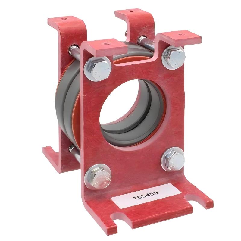
Allen-Bradley 1321-M048 Common Mode Choke Installation Guide (Setup & Commissioning)
Allen-Bradley 1321-M048 Common Mode Choke installation problems are usually caused by incorrect cable routing, improper grounding, or unsuitable motor cable installation rather than a defective choke component. In variable frequency drive (VFD) systems, the common mode choke is often installed correctly but fails to reduce electrical noise because the interference source, cable arrangement, or grounding path has not been analyzed properly.
The Allen-Bradley 1321-M048 Common Mode Choke is used in industrial motor drive applications to reduce common mode current, minimize electromagnetic interference (EMI), and improve system reliability when operating with AC drives and long motor cable distances.
Allen-Bradley 1321-M048 Common Mode Choke Application Overview
The 1321-M048 works as a passive filtering component installed in the motor power circuit of drive systems.
Typical installation structure:
AC Power
   |
Variable Frequency Drive
   |
1321-M048 Common Mode Choke
   |
Motor Cable
   |
AC Motor
Typical applications include:
- Conveyor drive systems
- Pump and fan applications
- Machine tools
- Packaging equipment
- Industrial automation panels
In one production line upgrade project, engineers installed a 1321-M048 common mode choke on a VFD-controlled conveyor motor.
Initial operating condition:
- Drive operation: Normal
- Motor running: Stable
- Nearby sensors: Intermittent signal errors
The maintenance team suspected sensor failure.
During commissioning analysis:
- Motor current waveform was checked
- Cable routing was inspected
- Noise interference was measured near signal wiring
The engineering team found that motor power cables and sensor cables were routed together inside the same cable tray.
After separating the cables and installing the choke correctly:
- Sensor communication became stable
- Signal interference disappeared
- No additional controller changes were required
The issue was installation practice, not hardware failure.
Allen-Bradley 1321-M048 Installation Preparation and System Planning
Before installing the common mode choke, engineers should evaluate the complete motor drive system.
Preparation checklist:
- Confirm drive power rating
- Verify motor cable length
- Check motor current requirements
- Review EMI risk points
- Inspect cabinet space and airflow
Important installation considerations:
| Inspection Item | Engineering Requirement |
|---|---|
| Choke location | Close to drive output |
| Cable arrangement | Correct conductor routing |
| Mechanical mounting | Secure installation |
| Grounding | Proper grounding path |
| Motor cable | Suitable insulation rating |
A common field mistake is installing the choke physically but leaving excessive cable length between the drive output and filtering component.
Allen-Bradley 1321-M048 Common Mode Choke Wiring Installation
Correct wiring is essential for effective noise reduction.
During installation, engineers should verify:
- Motor conductors pass through the choke correctly
- Cable direction follows the installation requirement
- Connections are tight
- Ground conductors are properly arranged
Incorrect installation examples:
- Only some motor phases pass through the choke
- Control cables are mixed with motor power wiring
- Grounding path is incomplete
In one machine application, engineers found:
Before correction:
- Encoder signal fluctuation: ±15%
- Drive fault frequency: 4 times/day
Inspection result:
- Motor conductors were not routed correctly through the choke
- Shield grounding was inconsistent
After correction:
- Encoder signal variation reduced significantly
- Drive operation remained stable for continuous production
Allen-Bradley 1321-M048 Drive System Setup and Noise Reduction Strategy
The common mode choke is only one part of the complete EMI control strategy.
Engineers should also verify:
- Drive parameter settings
- Carrier frequency
- Motor cable routing
- Control signal separation
- Shielding method
Typical diagnostic logic:
IF Drive_Operation = Normal
AND Signal_Noise = High

THEN

Check:
Cable Routing
Grounding
Common Mode Filtering
A practical engineering approach is to identify whether the interference comes from:
- Drive output switching
- Motor cable radiation
- Ground current circulation
- Poor signal cable separation
Allen-Bradley 1321-M048 Commissioning Validation and Performance Testing
After installation, engineers should verify system performance.
Electrical Testing
Check:
- Motor current stability
- Drive output condition
- Ground noise level
Machine Operation Testing
Verify:
- Sensor reliability
- Communication stability
- Drive fault history
Example commissioning results:
Before correction:
- Sensor communication loss: 10 events/shift
- Drive trips: occasional
After correction:
- Communication loss: 0 events
- Drive operation: stable for 7 days
A successful 1321-M048 installation requires correct filtering placement, proper wiring, and complete EMI control planning.