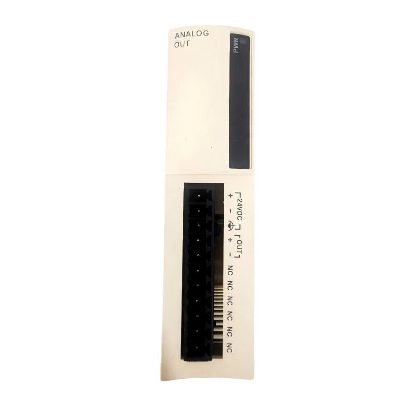
Schneider TWDAMO1HT Analog Output Module Installation Guide (Wiring & Commissioning)
Schneider TWDAMO1HT analog output module installation problems are usually caused by incorrect signal configuration, improper wiring methods, unsuitable output scaling, or incorrect PLC application settings rather than module hardware failure. In industrial control systems, an analog output module can communicate normally with the PLC while the connected actuator still operates incorrectly because the output signal type and field device requirements are not correctly matched.
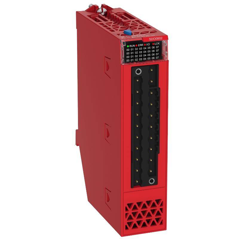
The Schneider TWDAMO1HT Analog Output Module is designed for Twido PLC systems and provides analog output capability for industrial control applications. It converts PLC digital values into voltage or current signals used by external devices such as variable frequency drives, proportional valves, motor controllers, and process regulators.
Schneider TWDAMO1HT Analog Output Module Application Overview
The TWDAMO1HT provides a connection between PLC control logic and analog field devices.
Typical control structure:
PLC Control Program
          |
          |
Schneider TWDAMO1HT Analog Output Module
          |
          |
0-10V / 4-20mA Analog Signal
          |
          |
Drive / Valve / Actuator / Controller
Common applications:
- Variable speed motor control
- Flow regulation systems
- Pressure control applications
- Temperature adjustment systems
- Industrial process equipment
Main functions:
- Digital-to-analog signal conversion
- Precise process control
- External device regulation
- PLC-based automation control
In practical automation systems, analog output modules are often used where digital ON/OFF control cannot provide sufficient process accuracy.
For example:
A water circulation system used a TWDAMO1HT module to provide speed reference control for a pump inverter.
During initial commissioning:
- PLC program: Running normally
- Module status: Normal
- Pump speed: Incorrect
The engineering team did not immediately replace the module.
The diagnostic process included:
- Measuring analog output voltage
- Checking PLC scaling values
- Reviewing inverter input requirements
- Inspecting signal wiring
Field measurement:
Before correction:
- PLC output value: Correct
- Expected signal: 0–10 VDC
- Actual output: Limited range
- Pump speed: Unable to reach target value
After reviewing the configuration, engineers discovered that the output scaling range did not match the inverter input requirement.
After adjustment:
- Analog output reached full range
- Pump speed followed commands correctly
- System commissioning completed successfully
The failure was caused by configuration mismatch rather than module damage.
Schneider TWDAMO1HT Installation Preparation and Control System Planning
Before installing the TWDAMO1HT analog output module, engineers should analyze the complete control loop.
Preparation requirements:
- Confirm PLC compatibility
- Identify field device input type
- Determine voltage or current output requirement
- Prepare shielded signal cables
- Define engineering scaling values
Installation checklist:
| Inspection Item | Engineering Requirement |
|---|---|
| PLC system | Compatible Twido platform |
| Output mode | Correct voltage/current selection |
| Signal cable | Shielded industrial cable |
| External device | Matching analog input |
| Power supply | Stable control voltage |
A common field mistake is selecting the analog output type without checking the receiving device.
Example:
A motor controller requiring 4–20 mA input will not operate correctly if the module is configured for voltage output.
Correct engineering practice:
PLC output specification → Signal cable → Device input specification
All three parts must match.
Schneider TWDAMO1HT Analog Output Module Wiring Installation
Proper wiring directly affects signal accuracy.
Analog Output Signal Wiring
Engineers should verify:
- Positive and negative terminals
- Signal polarity
- Cable shielding
- Grounding method
Recommended field practice:
- Use twisted shielded cable
- Separate analog cables from motor cables
- Avoid high-frequency interference sources
PLC Module Connection
Check:
- Module installation position
- Terminal tightening
- PLC power stability
During one machine commissioning project:
Initial condition:
- PLC logic was correct
- Analog output value changed
- Actuator response was unstable
The engineering team measured the signal:
- Output command: Stable
- Field voltage: Fluctuating
Further inspection found that the analog cable was installed together with a motor power cable.
After cable separation:
- Signal fluctuation disappeared
- Actuator movement became stable
- Machine operation improved
Schneider TWDAMO1HT Setup and System Configuration
The setup stage determines analog output accuracy.
Important configuration areas:
- Output channel settings
- Signal type selection
- Digital value range
- Engineering unit conversion
Typical control logic:
IF PLC_Command = Valid
AND Output_Mode = Correct
AND Wiring = Normal

THEN

Generate_Analog_Output
Engineers should verify:
- Minimum output value
- Maximum output value
- Intermediate control values
- Field equipment response
Common configuration mistakes include:
- Incorrect scaling
- Wrong signal range
- Incorrect engineering units
These problems may cause:
- Motor speed errors
- Valve positioning problems
- Process instability
Schneider TWDAMO1HT Commissioning Validation and Performance Testing
Final commissioning should test the complete analog control system.
Signal Calibration Test
Verify:
| PLC Command | Expected Output |
|---|---|
| Minimum value | Minimum analog signal |
| 50% command | Mid-range signal |
| Maximum value | Maximum analog signal |
Equipment Response Test
Check:
- Motor speed change
- Valve movement
- Process feedback
- Long-term stability
A successful Schneider TWDAMO1HT installation requires correct wiring, accurate scaling, and practical field validation.