Schneider ATS22D32S6 Soft Starter Installation Guide for Industrial Motor Control Systems
Schneider ATS22D32S6 soft starter installation issues are most commonly caused by incorrect line voltage wiring, wrong inside-delta vs in-line configuration, or improper motor current parameter setup, rather than internal thyristor failure. The ATS22 series is part of the Altistart 22 intelligent soft starter family, designed for medium-power 3-phase motor applications such as pumps, fans, compressors, and conveyors.
Schneider ATS22D32S6 Role in Motor Control Architecture
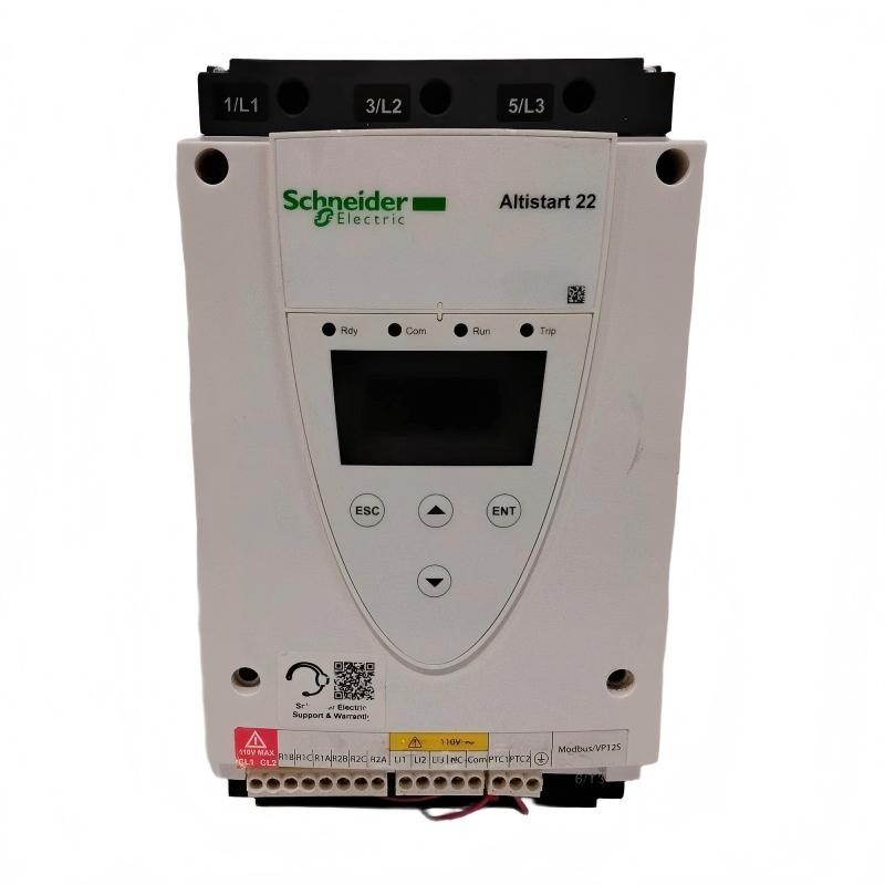
The Schneider ATS22D32S6 is an Altistart 22 soft starter rated for approximately 32A class operation, used for controlled acceleration and deceleration of asynchronous motors.
Core functions:
- Torque-controlled soft start / soft stop
- Inrush current limitation (typically ≤3.5 × In)
- Mechanical stress reduction on driven equipment
- Integrated bypass contactor for heat reduction after startup
- Motor protection (phase loss, overload, stalled motor detection)
Technical characteristics (field verified):
- Supply voltage: 208–600 V AC (3-phase)
- Control voltage: 230 V AC (varies by variant)
- Rated current: 32 A class configuration
- Motor power range: ~7.5–18.5 kW depending on voltage
- Start mode: current-limited torque control
Field insight: In a packaging conveyor system, replacing DOL start with ATS22 reduced peak starting current from ~6×In to ~3×In, eliminating repeated belt slip and gearbox shock.
Installation Conditions (Critical Engineering Requirements)
1. Power Circuit Configuration (Most Critical Step)
ATS22D32S6 supports both:
- In-line connection (standard mode)
- Inside-delta connection (only ATS22 Q variants in some cases)
Key checks:
- Verify correct L1 / L2 / L3 input wiring
- Confirm motor nameplate voltage matches configuration
- Ensure phase sequence is correct (1-2-3)
- Do not swap line and load terminals
Field failure case: A compressor repeatedly tripped on start due to reversed output wiring (motor connected to supply side), causing immediate overcurrent.
2. Control Circuit Integrity
- Control circuit is electrically independent from power circuit
- Use correct control voltage (230V or specified variant)
- Keep control wiring separated from power cables (minimum 80 mm recommended)
- Avoid shared neutral with inductive loads
Field observation: random “no start command response” was caused by voltage dip in shared control transformer feeding solenoids and soft starter simultaneously.
3. Thermal and Cabinet Conditions
- Mount vertically within ±10°
- Ensure free airflow bottom-to-top
- Do not stack units vertically
- Maintain cabinet IP rating (IP20 requires enclosure)
In one water plant, overheating trips occurred due to stacked installation without airflow gap between soft starters.
Installation Procedure (Field Engineering Practice)
Step 1: Mechanical Installation
- Mount ATS22 on DIN rail or panel plate
- Ensure solid grounding connection
- Leave clearance for heat dissipation
- Avoid vibration zones near large motors
Step 2: Power Wiring
- Connect L1/L2/L3 supply input
- Connect T1/T2/T3 to motor terminals
- Verify torque-tight connections
- Ensure correct phase sequence
Step 3: Control Wiring
- Apply control supply (CL1–CL2)
- Connect start/stop inputs (PLC or pushbutton)
- Verify correct logic mode (2-wire / 3-wire)
Step 4: Parameter Setup
- Set motor rated current (In)
- Adjust acceleration ramp time (5–20 s typical)
- Set initial torque for high inertia loads
- Enable or verify bypass function
Commissioning Strategy (Engineering Logic)
Step 1: No-Load Start Test
- Run motor without load
- Confirm smooth ramp without current spikes
- Check stable bypass transition
Step 2: Loaded Start Validation
- Apply real mechanical load
- Observe current limitation behavior (~3–4 × In typical)
- Check mechanical shock reduction
Step 3: Repeated Start Stress Test
- Perform multiple start cycles
- Monitor thermal rise in thyristor section
- Verify no nuisance trips
Field case: In a pump station, overheating only appeared after 10+ starts/hour due to underestimated thermal duty cycle.