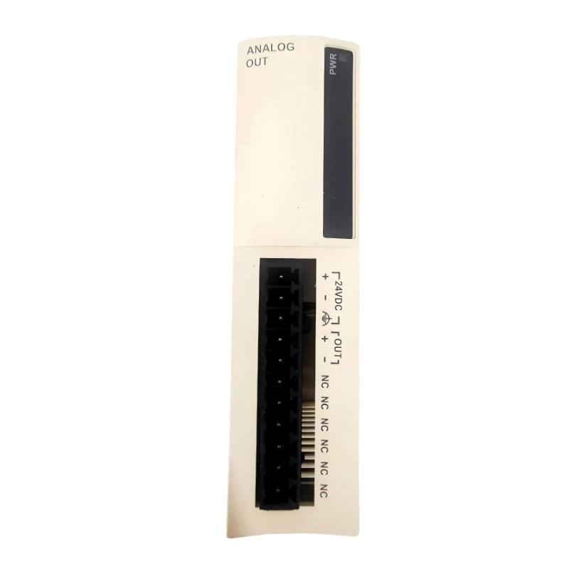
Schneider TWDAMO1HT Analog Output Module Troubleshooting Guide (Fault Diagnosis)
Schneider TWDAMO1HT analog output module faults are commonly caused by signal interference, incorrect scaling parameters, wiring problems, or field device mismatch rather than internal module failure. When an analog control problem occurs, engineers should diagnose the complete signal path instead of replacing the module immediately.
This article describes a field case where a TWDAMO1HT analog output signal caused unstable actuator control.
Schneider TWDAMO1HT Analog Output Fault Symptoms
Typical fault symptoms include:
- Output signal unstable
- Connected device responds incorrectly
- Motor speed fluctuates
- Valve position changes randomly
- PLC value does not match field operation
Field case:
A production line used a Schneider TWDAMO1HT analog output module to control a proportional control valve.
The operator reported:
- Valve movement was unstable
- Process pressure fluctuated
- PLC program showed no alarms
Initial assumptions:
- Analog module failure
- Valve controller problem
- PLC software issue
Engineers started troubleshooting from the entire analog loop.
Schneider TWDAMO1HT Fault Diagnosis Process and Signal Analysis
The diagnostic path was:
PLC Program
      |
      |
TWDAMO1HT Analog Output Module
      |
      |
Analog Signal Cable
      |
      |
Valve Controller
      |
      |
Process Equipment
Engineers checked:
- PLC output value
- Module operating status
- Analog signal measurement
- Final actuator response
Diagnostic results:
- PLC calculation: Normal
- Module status: Normal
- Output signal: Unstable
The problem was located between the module output and field device.
Schneider TWDAMO1HT Analog Signal Interference Investigation
Field measurements:
Before repair:
- PLC command: Stable
- Analog output: Fluctuating
- Valve position: Repeated movement
Engineers analyzed:
- Cable routing
- Shield connection
- Electrical environment
The investigation found:
- Analog signal cable was installed close to a high-power motor cable
- Electromagnetic interference affected signal quality
The module was generating the correct signal, but the field transmission path was disturbed.
Schneider TWDAMO1HT Root Cause Analysis and Recovery
The final root cause was improper signal cable installation.
Original condition:
- Analog signal worked correctly
- Control performance was stable
After electrical modification:
- Cable route changed
- Signal interference increased
Failure pattern:
Normal condition:
- Stable analog transmission
- Accurate actuator control
Fault condition:
- Signal noise increased
- Controller received incorrect reference
Engineering conclusion:
The failure was caused by installation conditions, not TWDAMO1HT hardware damage.
Schneider TWDAMO1HT Troubleshooting Repair and System Recovery
Corrective actions:
Signal Wiring Improvement
Performed:
- Moved analog cable away from power cables
- Improved shielding connection
- Checked terminal contact
Control System Verification
Tested:
- PLC output values
- Analog signal stability
- Valve response
Final results:
Before repair:
- Process fluctuation occurred frequently
- Operator adjustments were required
After repair:
- Stable analog output
- Accurate valve control
- Normal production restored
Schneider TWDAMO1HT Common Fault Patterns and Diagnostic Methods
No Analog Output Signal
Symptoms:
- Field device receives no control signal
Diagnosis:
- Check module power
- Verify terminal wiring
- Confirm PLC configuration
Incorrect Analog Output Value
Symptoms:
- Signal exists but value is incorrect
Diagnosis:
- Check scaling parameters
- Verify output range
- Compare PLC value with measured signal
Unstable Analog Signal
Symptoms:
- Output changes randomly
- Equipment response fluctuates
Diagnosis:
- Inspect cable routing
- Check shielding
- Separate signal and power wiring
Schneider TWDAMO1HT Long-Term Maintenance Strategy
For reliable analog output operation:
- Backup PLC configuration
- Record scaling parameters
- Inspect terminal connections
- Maintain cable shielding
- Monitor signal trends
A practical engineering rule:
“When troubleshooting a Schneider TWDAMO1HT analog output module, verify the complete analog control loop before replacing the module.”
Recommended troubleshooting sequence:
PLC value check → Module status inspection → Signal measurement → Wiring analysis → Field device verification → Final calibration test.