Allen-Bradley 1336-SN-SP10A Inverter Snubber Installation Guide (Wiring & Commissioning)
Allen-Bradley 1336-SN-SP10A inverter snubber installation issues are usually caused by incorrect replacement procedures, improper connection of suppression components, power circuit abnormalities, or failure to inspect related inverter components rather than the snubber itself. In industrial AC drive systems, an inverter snubber plays an important role in reducing voltage spikes and protecting switching components, so incorrect installation can lead to repeated drive faults even when the main control system appears normal.
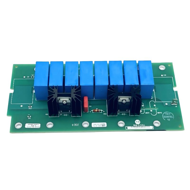
The Allen-Bradley 1336-SN-SP10A Inverter Snubber is a protection component used in Allen-Bradley 1336 series AC drives. It works with the inverter power section to suppress transient voltage disturbances generated during semiconductor switching, helping reduce stress on power switching devices such as IGBTs.
Allen-Bradley 1336-SN-SP10A Inverter Snubber Application Overview
The snubber circuit supports reliable operation of the inverter power stage by controlling switching transients.
Typical drive power structure:
AC Input||DC Bus Circuit||IGBT Inverter Section||1336-SN-SP10A Snubber Circuit||Motor Output
Main functions:
- Voltage spike suppression
- Switching stress reduction
- Semiconductor protection support
- Improved inverter reliability
Typical applications:
- Industrial motor drives
- Conveyor systems
- Machine automation equipment
- Pump and fan control systems
- Production line motor control
The snubber circuit becomes especially important in applications involving:
- High switching frequency
- Large motor loads
- Frequent acceleration and deceleration
- High electrical stress conditions
In one industrial drive repair project, engineers replaced an aging snubber component in an Allen-Bradley 1336 inverter system.
After replacement:
- Drive powered normally
- Motor started briefly
- DC bus fault appeared during operation
The first assumption was that the replacement snubber was defective.
The engineering team performed a complete power stage inspection:
- Checked snubber connection
- Measured DC bus condition
- Inspected IGBT switching section
- Reviewed fault history
Measured condition:
Before correction:
- Control voltage: Normal
- DC bus voltage: Stable at standby
- Fault occurrence: During motor acceleration
Further investigation found that one power connection point had poor contact, causing abnormal switching stress.
After correcting the connection:
- DC bus fault disappeared
- Motor acceleration became stable
- Drive returned to normal operation
The problem was related to power circuit installation rather than the snubber component.
Allen-Bradley 1336-SN-SP10A Installation Preparation and Power Circuit Inspection
Before installing the inverter snubber, engineers should inspect the complete drive power section.
Preparation requirements:
- Confirm correct replacement component
- Disconnect input power completely
- Verify DC bus discharge
- Inspect surrounding power components
- Check inverter fault history
Installation checklist:
| Inspection Item | Engineering Requirement |
|---|---|
| Component type | Match Allen-Bradley 1336 drive configuration |
| DC bus | Fully discharged before service |
| Connection points | Correct terminal position |
| Power components | Check for abnormal damage |
| Cooling system | Verify normal condition |
A common maintenance mistake is replacing the snubber without checking why the original component failed.
Possible root causes include:
- IGBT degradation
- Excessive switching stress
- Loose power connections
- Motor-side electrical problems
Replacing only the snubber may result in repeated failure if the original cause remains.
Allen-Bradley 1336-SN-SP10A Inverter Snubber Wiring Installation
Correct installation ensures effective transient suppression.
Power Circuit Connection Verification
Engineers should check:
- Snubber terminals
- Connection polarity
- Mechanical mounting
- Contact condition
Poor connections may cause:
- Increased electrical stress
- Repeated inverter faults
- Power component overheating
Surrounding Component Inspection
Verify:
- IGBT module condition
- DC bus capacitor status
- Power terminals
- Motor output wiring
During one field troubleshooting case:
Initial condition:
- Snubber replaced
- Drive restarted successfully
- Fault returned after load operation
Engineering measurements:
- DC bus voltage: Normal
- Control system: Normal
- Power switching waveform: Abnormal
Inspection found:
- One inverter power connection had increased contact resistance
After repairing the connection:
- Switching operation stabilized
- Drive operated continuously
Allen-Bradley 1336-SN-SP10A Setup and Commissioning Verification
After installing the snubber component, engineers should verify inverter operation under real conditions.
Important checks:
- DC bus stability
- Motor acceleration response
- Fault history
- Power stage temperature
Typical diagnostic logic:
IF DC_Bus = StableAND Power_Connection = GoodAND Switching = NormalTHENEnable Reliable_Inverter_Operation
Engineers should monitor:
- Startup current
- DC bus behavior
- Acceleration performance
- Drive fault records
A snubber replacement should always include a complete inverter validation test.
Allen-Bradley 1336-SN-SP10A Commissioning Validation and Performance Testing
Final testing should confirm that the inverter power section operates correctly.
Electrical Test
Check:
- DC bus charging
- Switching stability
- Protection response
Motor Operation Test
Verify:
- Startup
- Acceleration
- Continuous running
- Load response
Example commissioning results:
Before correction:
- Drive faulted during acceleration
- Motor operation unstable
After correction:
- Stable inverter switching
- Normal motor output
- Reliable production operation
A successful Allen-Bradley 1336-SN-SP10A installation requires correct component replacement, power circuit inspection, and practical commissioning verification.