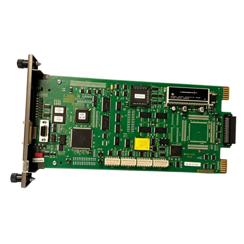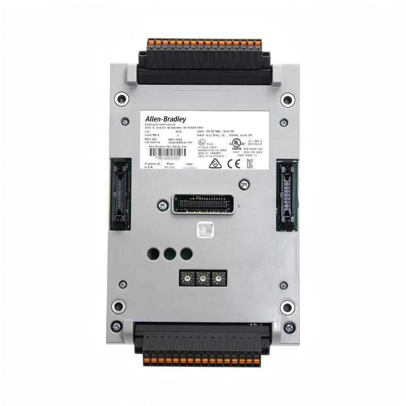
Allen-Bradley 1444-TB-A Dynamic Measurement Module Terminal Base Installation Guide (Wiring & Commissioning)
Allen-Bradley 1444-TB-A dynamic measurement module terminal base installation issues are usually caused by incorrect wiring, improper module seating, poor signal grounding, or incorrect connection between vibration monitoring devices and the measurement system rather than terminal base failure. In industrial condition monitoring applications, a terminal base provides the physical signal interface, and even a small connection problem can create inaccurate vibration data, unstable measurements, or false machine alarms.
The Allen-Bradley 1444-TB-A Dynamic Measurement Module Terminal Base is a connection interface designed for Allen-Bradley XM series monitoring systems and dynamic measurement applications. It provides the wiring foundation between field sensors, measurement modules, and industrial monitoring networks used for vibration, position, and machine condition analysis.
Allen-Bradley 1444-TB-A Dynamic Measurement Terminal Base Application Overview
The 1444-TB-A terminal base works as the connection point between monitoring sensors and dynamic measurement modules.
Typical condition monitoring architecture:
id="xmm01"Machine Equipment||Vibration Sensor / Probe||Allen-Bradley 1444-TB-A Terminal Base||Dynamic Measurement Module||PLC / Monitoring System
Typical applications:
- Rotating equipment monitoring
- Motor vibration analysis
- Pump and compressor condition monitoring
- Industrial machinery protection systems
- Predictive maintenance systems
Main functions:
- Sensor signal termination
- Module connection support
- Field wiring organization
- Simplified maintenance access
The terminal base is especially important in systems using:
- Accelerometers
- Velocity sensors
- Proximity probes
- Condition monitoring inputs
In one rotating equipment monitoring project, engineers installed an Allen-Bradley 1444-TB-A terminal base during a vibration monitoring system upgrade.
After commissioning:
- Monitoring module powered correctly
- Network communication was normal
- Vibration readings were unstable
The initial assumption was sensor aging.
The engineering team performed a field investigation:
- Checked sensor output
- Verified terminal wiring
- Measured signal stability
- Inspected terminal base installation
Measured condition:
Before correction:
- Sensor output: Stable
- Module communication: Normal
- Vibration trend: Sudden spikes
Further inspection found that one signal connection inside the terminal interface had insufficient tightening force.
After correcting the connection:
- Vibration waveform stabilized
- False alarms disappeared
- Monitoring system returned to normal
The issue was caused by installation quality rather than terminal base failure.
Allen-Bradley 1444-TB-A Installation Preparation and Monitoring System Planning
Before installing the 1444-TB-A dynamic measurement terminal base, engineers should review the complete monitoring system design.
Preparation requirements:
- Confirm compatible dynamic measurement module
- Verify sensor type
- Review wiring diagrams
- Identify signal channels
- Prepare shielded instrumentation cables
Installation checklist:
| Inspection Item | Engineering Requirement |
|---|---|
| Module compatibility | Match dynamic measurement system |
| Sensor wiring | Correct channel assignment |
| Signal cable | Suitable shielded cable |
| Grounding | Proper instrumentation grounding |
| Terminal connection | Secure and reliable |
A common field mistake is treating vibration measurement wiring like standard digital I/O wiring.
Dynamic measurement signals are sensitive to:
- Electrical noise
- Ground loops
- Poor shielding
- Loose contacts
Incorrect installation can result in:
- Incorrect vibration values
- Unstable waveforms
- False machine alarms
Allen-Bradley 1444-TB-A Terminal Base Wiring Installation and Signal Verification
Correct wiring is essential for accurate dynamic measurements.
Sensor Signal Connection Check
Engineers should verify:
- Sensor positive and negative terminals
- Signal return path
- Shield termination
- Terminal identification
Poor connections may cause:
- Signal interruption
- Noise interference
- Measurement drift
Mechanical Installation Inspection
Check:
- Terminal base seating
- Module locking position
- Connector alignment
During one field installation:
Initial condition:
- Vibration monitoring system online
- Sensor values fluctuated randomly
Engineering measurements:
- Sensor output: 8.5 mV/g stable
- Module input: Intermittent
- Alarm status: Abnormal
Inspection found:
- Terminal interface was not fully locked after maintenance work
After reseating the terminal base:
- Signal transmission stabilized
- Vibration trend matched actual machine condition
Allen-Bradley 1444-TB-A Setup and Dynamic Measurement System Configuration
The setup stage ensures that sensor signals are correctly interpreted by the monitoring system.
Important configuration checks:
- Channel assignment
- Sensor type selection
- Measurement range
- Alarm thresholds
Typical diagnostic logic:
id="logic1444"IF Sensor_Signal = StableAND Terminal_Base = SecureAND Channel_Config = CorrectTHENAccept_Measurement_Data
Engineers should compare:
- Physical wiring
- Module configuration
- Monitoring software settings
A mismatch between hardware wiring and software configuration can create incorrect condition monitoring results.
Allen-Bradley 1444-TB-A Commissioning Validation and Performance Testing
Final commissioning should verify measurement accuracy under real machine operation.
Sensor Signal Test
Check:
- Baseline vibration value
- Signal stability
- Channel response
Machine Condition Test
Verify:
- Normal operating vibration
- Alarm response
- Trend recording
Example commissioning results:
Before correction:
- Vibration data fluctuated
- Maintenance team received false warnings
After correction:
- Stable measurement signals
- Accurate condition monitoring
- Reliable predictive maintenance operation
A successful Allen-Bradley 1444-TB-A installation requires correct sensor wiring, secure terminal installation, and complete signal validation.