Siemens 6AG1132-6GD51-7BA0 Digital Output Module Installation Guide (Wiring & Commissioning)
Siemens 6AG1132-6GD51-7BA0 digital output module installation issues are usually caused by incorrect wiring, wrong output addressing, insufficient power supply conditions, or actuator compatibility problems rather than module hardware failure. In industrial automation projects, a digital output module may appear online in the PLC system while connected valves, contactors, or relays fail to respond because field-side configuration and electrical connections are not correctly matched.
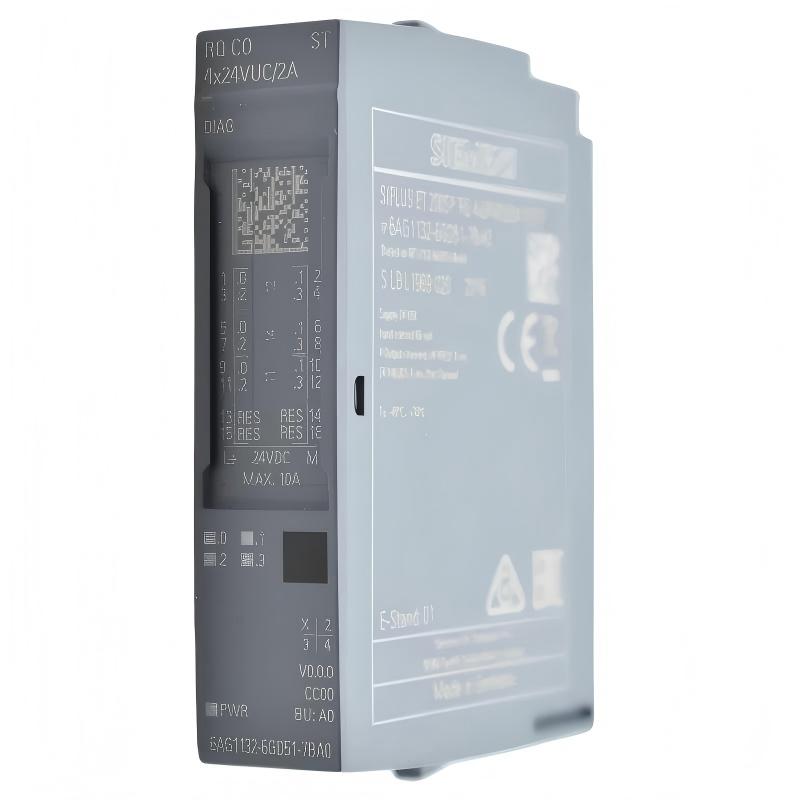
The Siemens 6AG1132-6GD51-7BA0 Digital Output Module is a ruggedized industrial digital output component designed for SIMATIC automation systems operating in demanding environments. It provides reliable switching of field devices such as solenoid valves, relays, contactors, and other binary actuators in PLC-based control applications.
Siemens 6AG1132-6GD51-7BA0 Digital Output Module Application Overview
The 6AG1132-6GD51-7BA0 provides the interface between the PLC controller and external actuators.
Typical automation structure:
PLC CPU||PROFINET / Backplane Communication||Siemens 6AG1132-6GD51-7BA0 Digital Output Module||Actuators / Valves / Relays / Contactors
Typical applications:
- Factory automation systems
- Machine control panels
- Remote I/O stations
- Process equipment
- Outdoor or harsh industrial installations
Main functions:
- Digital switching output control
- Field actuator interface
- Diagnostic feedback
- Industrial signal distribution
The SIPLUS-style rugged design of the 6AG1132-6GD51-7BA0 makes it suitable for applications where environmental resistance and long-term reliability are important.
Typical connected devices include:
- Pneumatic solenoid valves
- Motor contactors
- Indicator lamps
- Control relays
In one machine commissioning project, engineers installed a Siemens 6AG1132-6GD51-7BA0 digital output module for a valve control station.
During startup:
- PLC communication: Normal
- Module diagnostics: No major fault
- Several valves: Not responding
The initial assumption was actuator failure.
The engineering team checked:
- Output addressing
- Channel status
- Field voltage
- Wiring terminals
Measured condition:
Before correction:
- PLC output command: Active
- Module channel LED: ON
- Field actuator voltage: Missing
Further inspection found that the actuator power return wiring was incorrectly connected during cabinet modification.
After correcting the field wiring:
- Valve operation recovered
- Output commands executed correctly
- Commissioning completed successfully
The failure was caused by field wiring configuration rather than the digital output module.
Siemens 6AG1132-6GD51-7BA0 Installation Preparation and PLC System Planning
Before installing the digital output module, engineers should verify the complete automation architecture.
Preparation requirements:
- Confirm compatible SIMATIC hardware configuration
- Review PLC project file
- Identify output channel assignments
- Prepare field wiring diagrams
- Verify actuator electrical requirements
Installation checklist:
| Inspection Item | Engineering Requirement |
|---|---|
| Module compatibility | Match SIMATIC configuration |
| Output assignment | Confirm PLC addressing |
| Field voltage | Match actuator requirements |
| Wiring | Correct terminal identification |
| Power supply | Stable DC supply |
A common installation mistake is connecting a field device without checking its electrical characteristics.
Engineers should verify:
- Rated voltage
- Current consumption
- Inductive load characteristics
- Protection requirements
Incorrect actuator selection may result in:
- Output overload
- Channel protection activation
- Intermittent switching
Siemens 6AG1132-6GD51-7BA0 Digital Output Module Wiring Installation
Correct wiring ensures reliable signal transmission between PLC logic and field devices.
Output Channel Wiring Verification
Check:
- Output terminal assignment
- Positive and negative connections
- Field device polarity
- Common reference wiring
Incorrect wiring can cause:
- No actuator response
- Unexpected output behavior
- Channel diagnostics
Inductive Load Protection Inspection
For devices such as:
- Solenoid valves
- Contactors
- Relays
Engineers should verify:
- Suppression components
- Surge protection
- Load compatibility
During one field installation:
Initial condition:
- Digital output command was correct
- Solenoid valve did not activate
Engineering measurements:
- Module output status: Normal
- Control voltage: 24 VDC
- Load connection: Incorrect
Inspection found:
- The return path was connected to the wrong terminal group
After correction:
- Output switching became stable
- Valve response matched PLC commands
Siemens 6AG1132-6GD51-7BA0 Setup and System Configuration
The commissioning stage requires matching hardware wiring with PLC software configuration.
Important configuration checks:
- Hardware identification
- Module parameters
- Output address mapping
- Diagnostic settings
Typical diagnostic logic:
IF PLC_Command = TRUEAND Module_Status = ReadyAND Field_Voltage = AvailableTHENActivate_Output_Device
Engineers should compare:
- TIA Portal hardware configuration
- PLC output tags
- Physical terminal wiring
A mismatch between software addressing and field wiring is one of the most common causes of commissioning delays.
Siemens 6AG1132-6GD51-7BA0 Commissioning Validation and Performance Testing
Final commissioning should verify every output channel under actual operating conditions.
Digital Output Test
Check:
- Channel activation
- LED indication
- Field device response
System Operation Test
Verify:
- Machine sequence
- Interlock functions
- Emergency behavior
Example commissioning results:
Before correction:
- Multiple actuators unavailable
- Machine sequence interrupted
After correction:
- All output channels operated correctly
- PLC control restored
- Production testing completed
A successful Siemens 6AG1132-6GD51-7BA0 installation requires accurate configuration, correct wiring, and practical field validation.