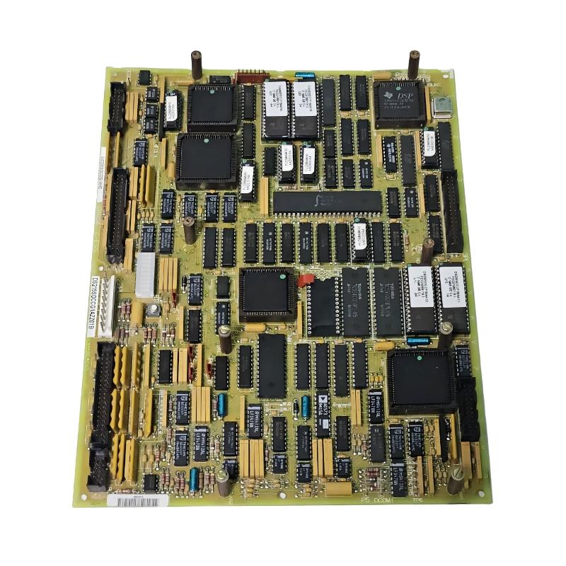
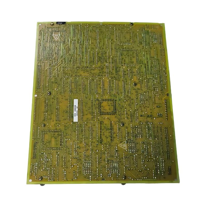
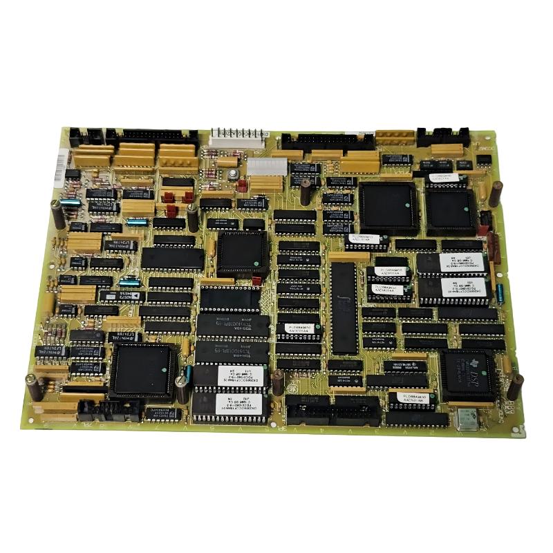
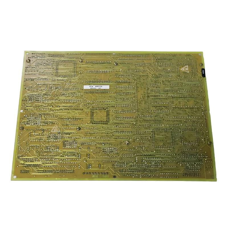
Brand:GE Fanuc PLC Item No.:DS200SDCCG1AHD Product Origin:USA Product Dimensions:330 × 220 × 25 mm Product Weight:0.45 kg Payment:T/T, Western Union, Credit Card Goods_stock:15 Shipping Port:Xiamen, China Lead Time:1-3 Days Condition:Brand New And Original Warranty:1 Year Certificate:COO
The GE DS200SDCCG1AHD Mark V Drive Control Board is a dedicated control-system PCB designed for GE industrial drive applications. It belongs to the DS200 family and is associated with the Mark V generation of GE control hardware used in demanding industrial environments.
The SDCC, or Serial Drive Control Board, forms part of the electronic control path between the drive-control logic and associated system components. Rather than functioning as an independent drive, the board provides the processing and interface resources necessary for controlling and monitoring drive-related equipment.
In a typical installation, the board works alongside other control and interface hardware. Control commands, feedback signals, and system information must be exchanged reliably between the different sections of the architecture. A problem with the drive-control board can therefore affect more than one individual signal and may appear as a broader drive or system fault.
When troubleshooting a suspected DS200SDCCG1AHD failure, technicians should first examine the complete signal chain. Power supply conditions, connectors, feedback devices, communication paths, and associated boards should be checked before condemning the PCB. This approach helps distinguish an actual board failure from an external wiring or instrumentation problem.
The AHD suffix should also be treated as part of the complete product identification. DS200 boards can share similar physical dimensions and general functions while differing in hardware revisions or configuration. Matching the exact part number is therefore important when sourcing a replacement.
For facilities maintaining older GE control equipment, the DS200SDCCG1AHD can serve as an important maintenance spare. Keeping the correct board available can shorten equipment-recovery time and reduce the operational impact of an unexpected drive-control failure.
Technical Specifications
Parameter
Specification
Brand
GE
Model
DS200SDCCG1AHD
Product Type
Mark V Drive Control Board
Functional Designation
SDCC
Board Description
Serial Drive Control Board
Product Family
GE DS200
Control Platform
GE Mark V
Primary Application
Industrial drive control
Primary Function
Drive control, processing, and signal interfacing
Dimensions
330 × 220 × 25 mm
Weight
0.45 kg / 0.99 lb
Installation
Compatible GE control-system assembly
Board Type
Industrial printed circuit board
Typical Use
Drive and motor-control applications
Recommended Related Models
For GE Mark V drive-control maintenance, the following models may be relevant when evaluating associated control hardware:
GE DS200SDCCG1A — Mark V Serial Drive Control Board
GE DS200SDCCG1AFD — Mark V Drive Control Board
GE DS200SDCCG1AHD — Mark V Drive Control Board
GE DS200SDCCG4A — Serial Drive Control Board
GE DS200SDCCG5A — Serial Drive Control Board
Different SDCC versions may have different revisions, functions, or system requirements. Always verify the complete part number before selecting a replacement.
Popular Related Models
Other GE DS200 and Mark V control boards relevant to industrial maintenance include:
GE DS200SDCCG1AHD Mark V Drive Control Board
GE DS200SDCCG1A Serial Drive Control Board
GE DS200TCQCG1BJG Mark V RST Overflow Plate
GE DS200TCQCG1BHF Mark V Analog I/O Expansion Board
GE DS200TCCAG2AJB I/O Board
GE DS200TCDAH1B Digital I/O Board
GE DS200TCRAG1A Relay Output Board
For replacement procurement, provide the complete DS200SDCCG1AHD part number and verify the installed system configuration, board revision, connectors, and application before installation.
Applications
The GE DS200SDCCG1AHD Mark V Drive Control Board is a specialized circuit board used in GE Mark V control architectures for drive and motor-control applications. As part of the DS200 family, it provides the processing, interface, and control functions required for coordinating drive-related operations within compatible GE industrial systems.
The SDCC board is designed to work with other components in the Mark V architecture, receiving control and feedback information while providing the appropriate interface for drive-control functions. Its role makes it particularly important in industrial installations where reliable motor and drive operation is essential to the overall process.
Typical applications include:
GE Mark V Speedtronic control systems
Industrial drive control
Motor control applications
Turbine auxiliary equipment
Industrial power-generation systems
Drive monitoring and feedback
Legacy GE automation systems
Control-board replacement and maintenance
Turbine and plant retrofit projects
Advantages
Dedicated Mark V drive-control architecture
The DS200SDCCG1AHD is designed specifically for GE Mark V systems, providing drive-control functionality within the established control architecture.
Integrated processing and control
The SDCC board incorporates the electronic circuitry required to process control information and coordinate drive-related functions.
Multiple interface capabilities
The board provides connections for communication, feedback, and control signals, allowing it to exchange information with other components of the system.
Suitable for legacy equipment support
For plants continuing to operate GE Mark V hardware, replacing an individual control board can be an efficient way to restore equipment functionality while retaining the existing system architecture.
Compact board-level construction
With dimensions of 330 × 220 × 25 mm, the board is designed for integration into the appropriate GE control cabinet or card assembly.
Maintenance-friendly replacement
The board-level format allows maintenance teams to target the failed control component rather than replacing an entire control system.
Technical FAQs
1. What is the GE DS200SDCCG1AHD?
The DS200SDCCG1AHD is a GE Mark V Drive Control Board used for drive-related control, processing, and interface functions within compatible GE industrial control systems.
2. What does SDCC stand for?
SDCC refers to the Serial Drive Control Board, a board designed to provide control and interface functions associated with GE drive applications.
3. What is the primary function of the SDCC board?
The board provides processing and interface functions required for drive control, including handling control signals, feedback information, and communication with associated system components.
4. Is the DS200SDCCG1AHD a standalone drive?
No. It is a control board used as part of a larger GE drive or control-system architecture. It should not be considered a complete variable-frequency drive.
5. What type of equipment can use an SDCC board?
SDCC boards are associated with GE industrial drive and control equipment, including systems integrated into larger Mark V installations.
6. What can cause an SDCC board to fail?
Possible causes include aging electronic components, electrical surges, power-supply problems, excessive temperature, contamination, connector faults, and problems originating from connected drive or field wiring.
7. What symptoms can indicate an SDCC board problem?
Potential symptoms include drive-control errors, loss of feedback, unexpected drive behavior, communication problems, intermittent operation, or system alarms associated with the affected control functions.
8. Should external wiring be checked before replacing the board?
Yes. Field wiring, connectors, power supplies, feedback devices, and associated interface boards should be inspected because an external fault can produce symptoms similar to a defective SDCC board.
9. Are the revision characters important when replacing the DS200SDCCG1AHD?
Yes. The complete part number should be matched. Different DS200SDCC versions can have different hardware revisions and configurations, so selecting a board based only on the SDCC designation is not recommended.
10. What precautions should be taken during replacement?
The equipment should be placed in the appropriate maintenance condition and electrically isolated according to site procedures. ESD protection should be used, and all connectors and configurable settings should be documented before removing the original board.