Allen-Bradley 20P41AD100RA0NNN PowerFlex DC Drive Installation Guide, Wiring and Commissioning
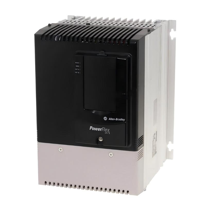
The Allen-Bradley 20P41AD100RA0NNN is a PowerFlex DC regenerative drive rated for a 480 VAC, three-phase input and 100 A output, with a 60 HP / 45 kW normal-duty rating. Its four-quadrant regenerative architecture makes the installation approach different from a basic non-regenerative DC drive because the incoming AC system, DC motor armature circuit, field supply, feedback, and regeneration path all need to be considered together.
Allen-Bradley 20P41AD100RA0NNN PowerFlex DC Drive Installation Overview
The 20P41AD100RA0NNN is a Frame A PowerFlex DC Drive designed for DC motor applications requiring controlled acceleration, speed regulation, braking, and regenerative operation.
Key configuration characteristics include:
| Parameter | Specification |
|---|---|
| Product | Allen-Bradley PowerFlex DC Drive |
| Catalog Number | 20P41AD100RA0NNN |
| Input Voltage | 480 VAC |
| Input Phase | 3-phase |
| Input Type | 6-pulse |
| Output Current | 100 A |
| Normal-Duty Rating | 60 HP / 45 kW |
| Motor Operation | Four-quadrant regenerative |
| Frame Size | A |
| Enclosure | IP20, NEMA/UL Type Open |
| Field Supply | Single-phase regulated |
| HIM | Blank plate / no HIM |
| Communication Module | Not included |
| Conformal Coating | Yes |
The drive also provides integrated support for DC tachometer and encoder feedback, allowing the commissioning engineer to select a feedback arrangement appropriate to the motor and application.
Preparing the 20P41AD100RA0NNN Installation
Before wiring begins, verify the drive catalog number against the motor nameplate and application requirements. The most important checks are not simply the motor horsepower and armature voltage. The field voltage, armature current, feedback device, braking requirements, and regenerative operating conditions must also match the system design.
A practical pre-installation checklist includes:
- Confirm 480 VAC three-phase supply compatibility.
- Verify the DC motor's rated armature current does not exceed the drive application rating.
- Confirm the motor field requirements.
- Identify whether the motor uses tachometer or encoder feedback.
- Check the grounding arrangement.
- Separate power and low-level feedback wiring.
- Confirm adequate cabinet ventilation.
- Inspect the drive for shipping damage or contamination.
- Verify that upstream protection is correctly sized.
Because this is an IP20/open-style drive, it should be installed inside a suitable electrical enclosure rather than treated as a standalone outdoor device.
20P41AD100RA0NNN Power and Motor Wiring Considerations
The power circuit should be designed around the complete DC drive system rather than the drive alone. Incoming three-phase AC feeds the PowerFlex DC converter, while the controlled output supplies the DC motor armature.
The field circuit is separately important because the 20P41AD100RA0NNN uses a regulated single-phase field supply.
During installation, keep these circuits physically organized:
- AC input power
- DC armature connections
- Motor field wiring
- Control I/O
- Tachometer or encoder feedback
- Communication wiring
- Protective earth
Feedback wiring should be routed away from high-current armature and AC conductors. Shielding and grounding should follow the selected feedback device and the PowerFlex installation requirements.
Do not use an improvised grounding arrangement simply to eliminate feedback noise. A clean grounding strategy is usually more effective than adding random bonding points.
Commissioning the Allen-Bradley 20P41AD100RA0NNN
The first commissioning stage should be performed without immediately applying full motor load.
After completing the wiring inspection, verify the programmed motor data against the actual motor nameplate. Pay particular attention to:
- Motor armature voltage
- Motor armature current
- Motor field voltage
- Motor field current
- Maximum and minimum speed
- Acceleration and deceleration
- Feedback type
- Feedback scaling
- Current limits
- Regenerative operating requirements
The motor should initially be operated at low speed. Observe armature current, field current, speed feedback, and motor direction.
A useful commissioning measurement sequence is:
Commanded speed → actual speed → feedback signal → armature current → motor response
If the commanded speed is stable but the actual-speed signal oscillates, investigate the feedback circuit before changing the speed regulator gains.
System Configuration for Regenerative Operation
The major commissioning difference between a regenerative and non-regenerative DC drive is the treatment of braking and reverse energy flow.
During deceleration, the DC motor can operate as a generator. Instead of dissipating all braking energy through a resistor, a regenerative PowerFlex DC drive can return energy through the AC supply.
This makes the AC supply configuration particularly important.
For a four-quadrant application, confirm:
- Forward motoring operation
- Forward regeneration
- Reverse motoring
- Reverse regeneration
- Correct motor field polarity
- Correct armature polarity
- Stable speed feedback
A system that runs correctly in forward motoring mode has not necessarily completed regenerative commissioning.
Typical 20P41AD100RA0NNN Commissioning Case
Consider a 60 HP DC motor connected to a mechanical load with frequent acceleration and deceleration.
During initial testing, the motor runs normally at 500 rpm. The armature current is approximately 42 A. When the speed command is increased to 900 rpm, current rises to about 68 A and the motor reaches the requested speed smoothly.
During deceleration, however, the DC bus behavior becomes unstable and the drive intermittently reports a regenerative-related fault.
Instead of immediately increasing the current limit, the engineer checks the regeneration path and AC supply conditions. The incoming three-phase voltage is measured at approximately 477 VAC, 478 VAC, and 476 VAC phase-to-phase, indicating that the supply itself is reasonably balanced.
The investigation then moves toward the motor operating condition, regeneration configuration, and control parameters.
This illustrates an important Fault Diagnosis principle: a regenerative fault during deceleration should not automatically be interpreted as an overload fault. The drive is operating in a fundamentally different energy-flow condition during regeneration.
Allen-Bradley 20P41AD100RA0NNN Installation Verification
Before releasing the equipment for production, verify:
- Motor rotation direction
- Armature current at operating speed
- Field current
- Speed feedback stability
- Acceleration response
- Deceleration response
- Regenerative response
- Emergency-stop behavior
- Control input response
- Communication status, if an optional communication module is installed
Record the normal operating current and feedback values. These baseline measurements are extremely useful for future Troubleshooting and preventive maintenance.