Allen-Bradley 20P41AD100RA0NNN Troubleshooting Guide: DC Drive Fault Diagnosis and Repair
The Allen-Bradley 20P41AD100RA0NNN troubleshooting process should begin by determining whether the problem originates in the AC supply, DC motor circuit, field circuit, feedback system, control configuration, or regenerative operating condition. Randomly replacing the drive is rarely the most efficient Fault Diagnosis method.
20P41AD100RA0NNN Troubleshooting Starts With Operating Behavior
For a PowerFlex DC Drive, the symptom often provides more information than the fault indication itself.
For example:
- Drive powers up but motor does not rotate → investigate enable, field, reference, interlocks, and armature output.
- Motor rotates but speed is unstable → investigate feedback and regulation.
- Motor runs normally but trips during acceleration → investigate current demand and mechanical load.
- Motor runs normally but trips during deceleration → investigate regeneration.
- Drive repeatedly loses speed feedback → inspect tachometer/encoder wiring.
- Drive trips immediately after a motor replacement → compare motor parameters and feedback configuration.
The diagnostic sequence should therefore follow the energy and control path instead of starting with component replacement.
Diagnosing a 20P41AD100RA0NNN No-Run Condition
When the drive is powered but the DC motor does not start, first establish whether the drive has received a valid run command.
Check the control circuit for:
- Run/stop command
- Drive enable
- External interlocks
- Fault reset status
- Speed reference
- Field enable
- Control power
If the run command is present but the motor remains stationary, measure the relevant control signals and determine whether the drive is intentionally blocking armature output.
Do not immediately assume that the power section has failed.
A useful diagnostic distinction is:
No command → no output expected
versus
Valid command + healthy field + no armature response → investigate drive output/control circuitry
20P41AD100RA0NNN Speed Feedback Fault Diagnosis
Speed feedback is particularly important when the drive is operating in a closed-loop configuration.
A common symptom is a motor that starts normally but begins hunting as speed increases.
For example, a field-style diagnostic case may show:
- Commanded speed: 1000 rpm
- Actual speed: oscillating between 930 and 1070 rpm
- Armature current: 35–52 A
- Tachometer signal: intermittently unstable
- Motor mechanical condition: normal
In this situation, increasing the regulator gain can make the symptom worse.
The engineer should inspect the tachometer/encoder wiring, shielding, connector condition, grounding, and feedback scaling first.
If the feedback signal itself is unstable, regulator adjustment is treating the symptom rather than the root cause.
20P41AD100RA0NNN Overcurrent Troubleshooting
An overcurrent condition can originate from either the electrical system or the mechanical load.
Check:
- Motor armature wiring.
- Motor brushes and commutator.
- Mechanical coupling.
- Gearbox or driven machine.
- Acceleration time.
- Current limit settings.
- Motor nameplate data.
- Armature output condition.
A useful field comparison is to record current at several operating points.
For example, if the motor normally draws 38 A at 700 rpm but suddenly requires 62 A at the same speed and load, the change is more significant than the absolute current value.
That trend can point toward mechanical resistance, motor deterioration, or an incorrect operating condition.
Regenerative Fault Diagnosis During Deceleration
A particularly important troubleshooting scenario for the 20P41AD100RA0NNN is a fault that occurs only during deceleration.
If forward motoring is normal but the drive faults whenever the speed command ramps downward, inspect the regenerative operating conditions.
Check:
- Deceleration rate
- Mechanical inertia
- Regenerative load
- AC supply condition
- Motor field condition
- Armature circuit
- Drive configuration
A practical test is to increase the deceleration time within the application's safe operating limits. If the fault disappears when the deceleration ramp is significantly extended, the problem may be associated with regenerative energy demand rather than normal motoring current.
This does not prove that the drive is defective. It indicates that the regeneration condition requires further analysis.
20P41AD100RA0NNN Field Circuit Troubleshooting
The field supply deserves separate attention because the motor field directly affects DC motor operation.
A weak or missing field can produce abnormal speed behavior, poor torque performance, or a field-related fault depending on the configuration.
During troubleshooting, compare the measured field voltage and current with the motor's nameplate requirements.
For example, if the expected field current is approximately 3.0 A but measurement shows only 1.1 A under normal operating conditions, investigate:
- Field wiring
- Field protection
- Field connections
- Motor field winding
- Drive field supply
- Parameter configuration
Do not compensate for a field-circuit problem by simply increasing other drive parameters.
DC Motor Heating With the 20P41AD100RA0NNN
Motor heating is another condition that should be evaluated from both electrical and mechanical perspectives.
If armature current remains substantially above the historical baseline, check the mechanical load first.
If current is normal but the motor temperature continues rising, inspect ventilation, bearings, brushes, commutator condition, and cooling airflow.
For example:
| Measurement | Normal Baseline | Fault Condition |
|---|---|---|
| Armature current | 41 A | 43 A |
| Speed | 900 rpm | 900 rpm |
| Field current | 2.8 A | 2.8 A |
| Motor housing temperature | 61°C | 79°C |
| Cooling airflow | Normal | Reduced |
This pattern points more strongly toward a cooling or mechanical issue than an obvious armature overload.
20P41AD100RA0NNN Intermittent Fault Investigation
Intermittent faults are often harder to diagnose because the equipment may operate normally when the technician arrives.
For these cases, record:
- Fault occurrence time
- Motor speed
- Armature current
- Field current
- Speed reference
- Actual speed
- AC input voltage
- Ambient temperature
- Mechanical load condition
If the fault consistently appears after 30–40 minutes of operation, thermal effects should be considered.
If it occurs only during high-speed operation, feedback integrity becomes more important.
If it appears only during rapid deceleration, regenerative behavior should move toward the top of the diagnostic list.
20P41AD100RA0NNN Repair Decision: Drive or External Equipment?
A drive should not automatically be sent for repair whenever a fault appears.
A better Fault Diagnosis sequence is:
Supply → Field → Motor → Feedback → Control → Regeneration → Drive hardware
If all external conditions are confirmed healthy and the fault remains repeatable under controlled testing, the drive itself becomes a stronger suspect.
Before replacing or repairing the drive, document the original parameter configuration and wiring. This prevents a second failure caused by configuration differences after replacement.
20P41AD100RA0NNN Technical FAQ
1. What type of drive is the Allen-Bradley 20P41AD100RA0NNN?
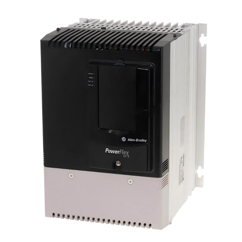
It is a PowerFlex DC regenerative drive designed for controlled DC motor applications and four-quadrant operation.
2. What is the input voltage of the 20P41AD100RA0NNN?
The drive uses a 480 VAC, three-phase input configuration.
3. What is the output current rating?
The catalog number corresponds to a 100 A DC output rating and a 60 HP / 45 kW normal-duty rating at the specified input conditions.
4. Is the 20P41AD100RA0NNN regenerative?
Yes. It is a four-quadrant regenerative PowerFlex DC Drive.
5. What does four-quadrant operation mean?
It allows the DC motor system to operate in both motoring and regenerative conditions in forward and reverse directions.
6. Does the drive include a HIM?
This specific catalog number is configured with a blank plate rather than an included HIM.
7. Can the drive use encoder feedback?
The PowerFlex DC platform supports encoder feedback as part of its feedback capabilities, depending on the installed configuration.
8. Why can a regenerative fault occur only during deceleration?
Deceleration can force energy from the motor and mechanical load back through the regenerative converter. Excessive regenerative demand or an unsuitable configuration can therefore produce a fault even when motoring operation is normal.
9. What should be checked when motor speed fluctuates?
Start with the speed feedback signal, feedback wiring, grounding, shielding, feedback scaling, and motor mechanical condition before changing regulator tuning.
10. What is the safest approach to repairing a 20P41AD100RA0NNN?
Use qualified personnel and appropriate lockout/tagout procedures, verify that hazardous voltage has been removed, document the original configuration, and isolate the fault between the external motor/control system and the drive before replacing internal components.