Siemens 6AG1592-6EF00-2AA0 Coding Element Installation Guide (Hardware Setup & Commissioning)
Siemens 6AG1592-6EF00-2AA0 Coding Element Installation for Industrial Automation Systems
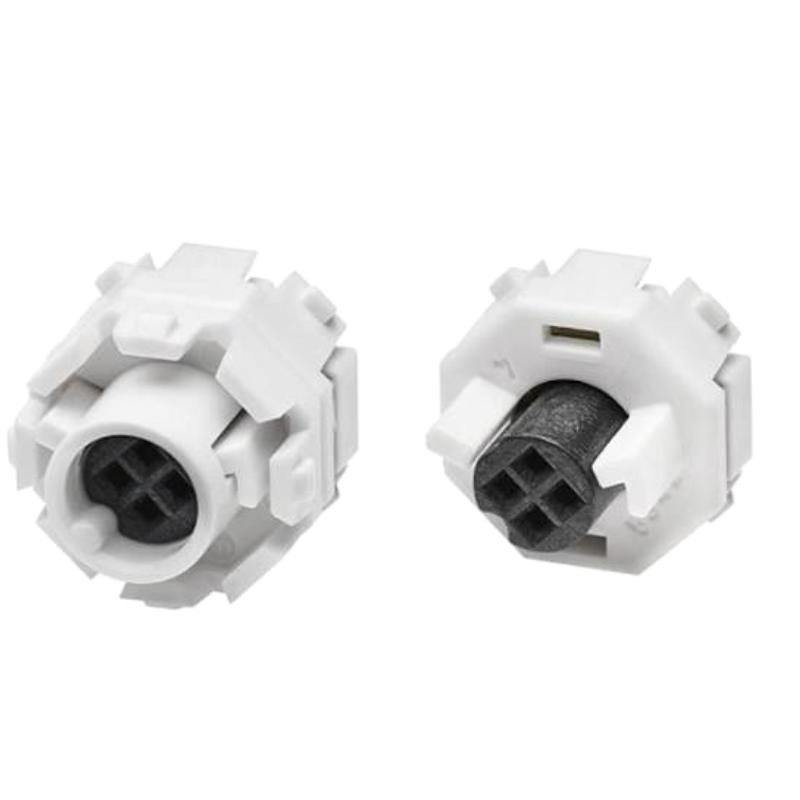
The Siemens 6AG1592-6EF00-2AA0 Coding Element installation process focuses on correct component identification, mechanical positioning, and verification of the associated connection or module arrangement. In industrial automation systems, coding components help prevent incorrect connections or mismatched hardware configurations, depending on the specific connector and system design.
Before installation, confirm the exact function of the 6AG1592-6EF00-2AA0 against the applicable Siemens product documentation. Coding elements can serve different purposes across product families, so their installation position and compatibility should not be inferred from the part name alone.
A reliable installation process should follow this sequence:
Identify Component → Verify Compatibility → Inspect Connection → Install Coding Element → Confirm Assembly → Validate System
Siemens 6AG1592-6EF00-2AA0 Coding Element Pre-Installation Checks
Before installing the Siemens 6AG1592-6EF00-2AA0, verify the complete order number and identify the hardware assembly for which it is intended.
Important checks include:
Confirm the product designation and intended application.
Verify compatibility with the mating connector or module.
Check the mechanical interface for damage or contamination.
Review the applicable assembly instructions.
Ensure the equipment is in a safe state before maintenance.
Do not select a coding element based only on physical appearance. Components that look similar may have different mechanical keying or compatibility requirements.
Inspection Item | Purpose |
|---|---|
Order number | Prevent incorrect component selection |
Mating hardware | Confirm compatibility |
Mechanical interface | Identify damage or obstruction |
Assembly documentation | Verify installation position |
Existing configuration | Avoid mismatched replacement parts |
Siemens 6AG1592-6EF00-2AA0 Coding Element Mechanical Installation
Mechanical accuracy is important when fitting a coding element. An incorrect position or forced installation can damage the element or the mating component.
Before assembly, inspect the contact area and surrounding housing. Remove loose debris using a method appropriate for the equipment, and do not modify the coding element to make it fit.
A practical installation workflow is:
Inspect Component
       ↓
Confirm Mating Part
       ↓
Check Orientation
       ↓
Install According to Instructions
       ↓
Inspect Mechanical Engagement
       ↓
Record Completion
The element should fit according to the manufacturer's specified method. If resistance is unexpected, stop and recheck the part number, orientation, and mating interface rather than applying additional force.
Siemens 6AG1592-6EF00-2AA0 Hardware Compatibility and System Setup
The 6AG1592-6EF00-2AA0 should be evaluated within the complete hardware assembly. Correct coding alone does not establish that the connected equipment is electrically or functionally compatible.
During Setup, verify:
Correct associated hardware
Correct connector or assembly position
Matching mechanical coding arrangement
Correct installation documentation
Absence of visible damage
If the coding element is part of a replacement or maintenance activity, compare the new component with the original assembly and confirm that the original hardware arrangement is documented correctly.
Do not assume that the element changes PLC software configuration or electrical behavior unless the product documentation explicitly identifies that function.
Siemens 6AG1592-6EF00-2AA0 Installation Verification and Commissioning
After installation, check that the component is correctly positioned and that the associated assembly can be completed according to the manufacturer's instructions.
Commissioning checks should include:
Visual inspection
Mechanical engagement verification
Confirmation of the correct part number
Inspection of associated connectors
System-level verification where applicable
If the element belongs to an electrical connection assembly, complete the relevant electrical checks before energizing the equipment. If it is purely mechanical, verify the specified mechanical function instead of assuming that an electrical test is required.
Siemens 6AG1592-6EF00-2AA0 Installation Case: Incorrect Coding Component
During a maintenance intervention, an engineer may encounter a connector or assembly that cannot be fitted as expected after a replacement part has been selected.
A disciplined investigation should compare the original part number, replacement part number, mating component, and installation orientation. If the replacement element does not match the documented configuration, stop the assembly and verify compatibility.
After installing the confirmed correct component, inspect the mechanical fit and perform the applicable system checks before returning the equipment to service.
The key engineering principle is to resolve a coding mismatch through identification and compatibility verification—not by forcing, filing, or otherwise modifying the component.
Siemens 6AG1592-6EF00-2AA0 Coding Element Maintenance Recommendations
For long-term maintenance reliability:
Keep the full order number in spare-parts records.
Store small coding components in labeled packaging.
Prevent contamination and mechanical damage.
Verify compatibility before replacement.
Update maintenance records after assembly changes.
Correct identification and careful installation help reduce assembly errors and avoid damage to associated Siemens automation hardware.