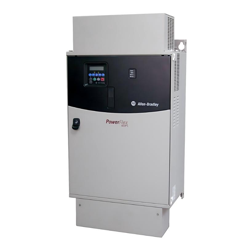
Allen Bradley 22C-D260A103 PowerFlex 400 Troubleshooting Guide (Overcurrent Fault Diagnosis)
When an Allen Bradley 22C-D260A103 PowerFlex 400 AC Drive trips on an overcurrent fault during fan or pump operation, the cause may involve excessive mechanical load, incorrect motor parameters, a short circuit, unsuitable acceleration settings, or motor-cable problems. With a rated output current of 260A and a motor power rating of 200 HP, troubleshooting should begin with a systematic inspection of the electrical circuit and driven equipment rather than repeated fault resets.
1. Recognizing Overcurrent Symptoms on the 22C-D260A103
Overcurrent problems can occur at different stages of operation:
The drive trips immediately after receiving a run command.
The motor starts but trips during acceleration.
The drive operates at low speed but trips as speed increases.
The fault appears when the pump or fan is under process load.
The drive operates normally without the mechanical load but trips when the equipment is coupled.
The timing of the trip provides useful diagnostic information. An immediate trip may indicate an electrical connection problem or short circuit, while a trip during acceleration may involve motor data, ramp settings, load inertia, or mechanical resistance.
Record the displayed fault code and operating conditions before resetting the drive.
2. Inspecting the Motor and Power Circuit
Before changing drive parameters, isolate the equipment and inspect the motor circuit.
Motor Cable Inspection
Look for damaged insulation, crushed cable sections, moisture ingress, loose terminals, and signs of overheating.
A short circuit between phases or between a phase and ground can cause an immediate drive trip.
Motor Terminal Connections
Confirm that the motor terminal links match the required voltage and winding configuration. Incorrect star/delta connections can result in abnormal current and poor motor performance.
Motor Insulation Testing
If a ground fault or insulation problem is suspected, test the motor and cable using an appropriate procedure with the drive fully disconnected.
Never apply an insulation tester directly to the drive's electronic output terminals.
Output-Side Equipment
Inspect output contactors, reactors, filters, and disconnect devices. Their suitability and switching sequence must follow the manufacturer's instructions.
Do not operate a motor output contactor while the drive is producing output unless the system is specifically designed for that operation.
3. Overcurrent During Acceleration: Checking Ramp Settings
A fan or pump may require significant torque to accelerate, particularly when the driven equipment has high inertia or starts under unfavorable process conditions.
If the 22C-D260A103 trips during acceleration, investigate:
The configured acceleration time.
The condition of the fan, pump, coupling, and bearings.
Whether the equipment is obstructed.
Whether the motor nameplate data is correctly configured.
Whether the acceleration ramp is appropriate for the actual load.
An acceleration ramp that is too short can demand excessive current. Increasing the acceleration time may help, but it should not be used to conceal a mechanical obstruction or incorrectly sized motor.
For pump systems, inspect the valves, fluid conditions, and process pressure. For fan systems, check dampers, belts, bearings, and airflow restrictions.
4. Verifying Motor Nameplate Data and Drive Parameters
Incorrect motor data can cause poor drive performance and inappropriate protection behavior.
Compare the motor nameplate with the corresponding PowerFlex 400 settings.
Motor Information | What to Verify |
|---|---|
Rated Voltage | Matches the motor connection and application |
Rated Current | Entered correctly for the motor |
Rated Frequency | Matches the motor nameplate |
Rated Speed | Consistent with the motor's rated operating conditions |
Motor Connection | Star/delta links match the intended voltage |
Control Mode | Suitable for the motor and load |
Do not enter the drive's maximum current rating as the motor's rated current. Motor parameters must be based on the actual motor nameplate.
If the motor has been replaced, review the complete parameter configuration rather than changing only one current-related value.
5. Overcurrent After the Motor Reaches Operating Speed
If the drive starts successfully but trips after running for some time, investigate changes in load and operating conditions.
Possible causes include:
A pump operating against excessive pressure.
A blocked or partially obstructed pump or pipe.
Fan damper changes that increase the load.
Worn bearings or mechanical friction.
Motor cooling problems.
Excessive process demand.
Incoming supply voltage imbalance.
Measure the drive's output current under normal and fault-producing conditions. Compare the readings with the motor nameplate current and the applicable drive operating limits.
For pump and fan applications, also record process conditions at the time of the trip. Sudden changes in pressure, flow, damper position, or mechanical resistance may explain the increase in current.
6. Distinguishing Overcurrent, Ground Fault, and Motor Overload
Different protective trips indicate different problems. They should not be treated as the same failure.
Observed Condition | Investigation Priority |
|---|---|
Immediate overcurrent trip | Check output wiring, motor cable, and motor insulation |
Trip during acceleration | Check ramp time, motor data, and mechanical load |
Trip at higher operating speed | Check process load and motor current |
Ground fault indication | Inspect motor cable and motor insulation to ground |
Motor overload trip | Check motor current, load, cooling, and overload settings |
DC bus overvoltage during stopping | Review deceleration ramp and regenerative energy |
Use the actual fault code and the PowerFlex 400 technical documentation to identify the protection function that operated.
7. Checking RS485 Communication and Control Commands
A communication or control issue may cause unexpected operating behavior, although it should not automatically be assumed to be the cause of an electrical overcurrent trip.
If the drive receives run and speed commands through RS485, verify:
The communication link remains stable.
The drive receives the intended speed reference.
The command source is configured correctly.
The connected controller is not issuing sudden or unrealistic speed changes.
Communication-loss behavior is configured appropriately.
If the supervisory system supports data logging, compare the speed reference and output current. A sudden speed-reference change immediately before the trip may indicate a control-sequence problem.
8. A Safe Troubleshooting Procedure for the 22C-D260A103
A systematic diagnostic process helps isolate the cause without unnecessary component replacement.
Preserve fault information
Record the fault code, operating frequency, output current, running time, and process conditions.
Isolate the equipment
Follow the site's lockout/tagout procedure. Allow the DC bus to discharge and verify the absence of hazardous voltage according to the manufacturer's instructions before touching power terminals.
Inspect the motor circuit
Check motor cables, terminals, grounding, and the motor itself. Perform insulation testing only with the motor and cable disconnected from the drive.
Inspect the driven equipment
Check for mechanical binding, bearing problems, blocked flow paths, abnormal pressure, or fan restrictions.
Review drive settings
Compare motor nameplate data, acceleration and deceleration times, and control-source configuration with the actual application.
Perform a controlled restart
After correcting the identified cause, restart under controlled conditions and monitor current, speed, and process response. If the fault returns, stop and continue diagnosis instead of repeatedly resetting the drive.
9. When Should the PowerFlex 400 Drive Be Repaired or Replaced?
Drive replacement should be considered only after external wiring, motor, supply, and mechanical causes have been investigated.
Further drive-level inspection may be necessary if:
The same fault occurs with a verified motor and cable circuit.
The drive shows signs of damaged power terminals or internal components.
Abnormal operation continues despite correct motor data and a suitable load.
The drive cannot complete its normal startup sequence despite verified supply conditions.
Internal inspection and power-component repair should be performed by qualified personnel familiar with high-voltage variable frequency drives. The DC bus can retain hazardous energy after incoming power is disconnected.
Before replacing the unit, back up the parameter configuration and record the complete catalog number, series, firmware information, and communication settings.
10. Troubleshooting FAQs for Allen Bradley 22C-D260A103
Q1: Why does the 22C-D260A103 trip on overcurrent when starting a pump?
Possible causes include a shorted motor cable, incorrect motor connection, excessive mechanical resistance, incorrect motor data, or an acceleration ramp that is too aggressive.
Q2: Why does the drive trip only when the fan reaches a higher speed?
The motor load may increase at higher speed, or the fan may have mechanical friction, airflow restrictions, or an unsuitable operating point. Compare current readings at different speeds.
Q3: Can incorrect motor nameplate settings cause overcurrent problems?
Yes. Incorrect voltage, current, frequency, or speed data can affect drive operation and protection behavior. Verify all motor-related settings against the actual nameplate.
Q4: Should I increase the acceleration time to eliminate an overcurrent fault?
A longer acceleration time may reduce current demand during startup. However, first check for mechanical binding, incorrect motor wiring, and unsuitable motor data.
Q5: Can a damaged motor cable cause an immediate overcurrent trip?
Yes. Phase-to-phase or phase-to-ground insulation damage can create an electrical fault. Inspect and test the motor circuit with the drive isolated and disconnected.
Q6: Why does the drive run without the mechanical load but trip when the pump is connected?
The pump may have excessive starting torque, mechanical resistance, or abnormal process conditions. Inspect the coupling, bearings, hydraulic system, and motor sizing.
Q7: Can an RS485 communication problem cause an overcurrent trip?
A communication problem may lead to incorrect or unstable commands, but it does not automatically explain an electrical overcurrent fault. Check the actual fault code and monitor the speed reference.
Q8: Is a ground fault the same as an overcurrent fault?
No. They are different protection conditions. A ground fault generally indicates current flowing to earth through an unintended path, while an overcurrent fault indicates excessive current in the monitored circuit.
Q9: Why should the DC bus be checked before servicing the drive?
The DC bus capacitors can retain hazardous voltage after the AC supply is disconnected. Follow the manufacturer's discharge waiting time and verify voltage with an appropriate instrument before servicing.
Q10: What information is useful when requesting repair support?
Provide the complete catalog number, fault code, motor nameplate data, incoming voltage, operating current, parameter backup, and a description of when the fault occurs. These details help narrow down the likely failure area.