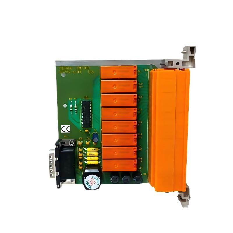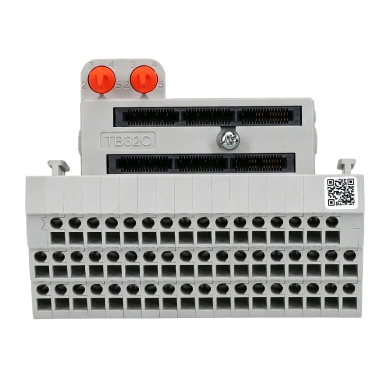
Siemens 6AG1592-6EF00-2AA0 Coding Element Troubleshooting Guide (Compatibility Fault Diagnosis & Repair)
Siemens 6AG1592-6EF00-2AA0 Coding Element Troubleshooting for Assembly Problems
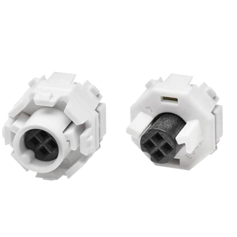
Siemens 6AG1592-6EF00-2AA0 Coding Element troubleshooting should begin with component identification and mechanical compatibility checks. If an assembly does not fit, locks incorrectly, or cannot be verified after maintenance, the first task is to establish whether the correct coding element and mating hardware have been selected.
Because the exact application determines the element's function, use the relevant Siemens documentation to confirm its intended position and role before attempting corrective work.
A practical Fault Diagnosis sequence is:
Assembly Symptom → Part Identification → Compatibility Check → Mechanical Inspection → Corrective Action → Verification
Siemens 6AG1592-6EF00-2AA0 Coding Element Fault Symptoms
Potential installation-related symptoms include:
Coding element does not fit the mating part.
Assembly cannot be completed correctly.
Mechanical engagement appears incomplete.
The installed component differs from the documented configuration.
A problem appears immediately after replacement or maintenance.
These symptoms do not automatically indicate that the coding element is defective. The issue may involve an incorrect spare part, wrong orientation, damage to the mating component, or an incomplete assembly procedure.
Siemens 6AG1592-6EF00-2AA0 Incorrect Part Number Diagnosis
When a replacement coding element does not match the existing assembly, compare the complete order numbers rather than relying on appearance.
Check the following:
Diagnostic Check | What to Confirm |
|---|---|
Original part | Full catalog number |
Replacement part | Exact order number |
Mating component | Correct product family |
Assembly instructions | Required position and orientation |
Component condition | Damage or deformation |
If the order numbers differ, verify whether the replacement is an approved alternative before proceeding.
Do not modify the element to force compatibility. Such changes can defeat the intended coding function or damage the mating assembly.
Siemens 6AG1592-6EF00-2AA0 Mechanical Fit Fault Diagnosis
If the correct component has been identified but the assembly still does not fit, inspect the mechanical interface.
Look for:
Bent or damaged features
Foreign material
Incorrect orientation
Worn locking features
Damage to the mating housing
A controlled inspection should be performed with the equipment in a safe state. Remove the component only according to the applicable maintenance instructions.
If the problem remains after cleaning and confirming orientation, compare the assembly with the manufacturer's drawings before deciding whether a component needs replacement.
Siemens 6AG1592-6EF00-2AA0 Troubleshooting Case: Assembly Fails After Replacement
Consider a maintenance case in which a small coding component is replaced during a scheduled shutdown, but the associated assembly can no longer be fitted correctly.
The initial observations are:
The replacement component appears physically similar.
The mating assembly was not reported faulty before maintenance.
The problem began immediately after the replacement.
The most useful next step is to compare the removed component's identification with the replacement's order number and confirm the specified installation orientation.
If the replacement is incompatible, obtain the correct component. If the part number is correct, inspect the mating interface for damage and verify the assembly procedure.
After correction, confirm that the assembly fits as specified and complete any required system-level checks before returning the equipment to operation.
Siemens 6AG1592-6EF00-2AA0 Damage and Replacement Assessment
Replace the coding element if inspection identifies damage or if the manufacturer specifies replacement after the relevant maintenance operation.
Before installing another component:
Confirm the exact part number.
Inspect the mating component.
Check the specified installation orientation.
Follow the approved assembly procedure.
Verify the completed assembly.
If the mating housing is damaged, replacing the coding element alone may not resolve the problem.
Siemens 6AG1592-6EF00-2AA0 Fault Repair Verification
After correcting an installation or compatibility problem, verify the original symptom rather than relying only on visual appearance.
Confirm that:
The correct component is installed.
Mechanical engagement meets the specified requirements.
No visible damage remains.
The associated hardware is correctly assembled.
Required system checks are complete.
Document the original problem, confirmed root cause, replacement part number, corrective action, and final inspection result.
Siemens 6AG1592-6EF00-2AA0 Coding Element Troubleshooting Best Practices
Reliable Siemens 6AG1592-6EF00-2AA0 Fault Diagnosis depends on accurate identification and controlled mechanical inspection. A coding element should not be forced into an assembly or modified to overcome a mismatch.
Start with the order number and manufacturer's installation documentation, then inspect orientation, mating hardware, and component condition. This process helps prevent unnecessary replacement, protects the associated equipment, and improves maintenance reliability.