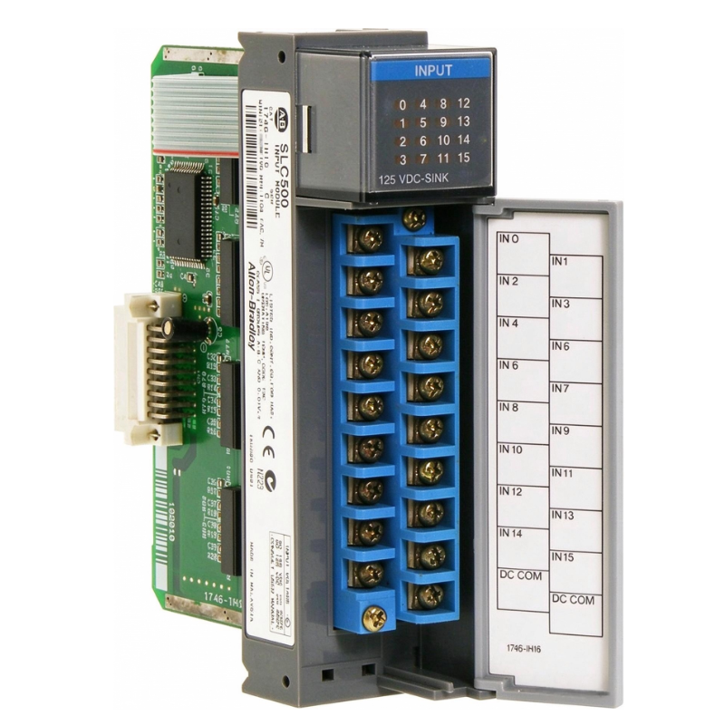
Allen Bradley 1746-IH16 Digital DC Input Module Installation Guide (Wiring & Setup)
Allen Bradley 1746-IH16 Input Module Installation Overview
The Allen Bradley 1746-IH16 digital DC input module requires correct input-voltage wiring, chassis installation, and SLC 500 system configuration to ensure reliable signal acquisition. During installation, the main engineering concerns are field-voltage compatibility, input-channel assignment, common-terminal wiring, and noise immunity. Incorrect wiring or an unsuitable DC supply can cause missing input signals, unstable status indication, or unexpected PLC logic behavior.
The 1746-IH16 is part of the Allen Bradley SLC 500 I/O family. It interfaces field-level DC signals with the PLC processor, allowing the controller to monitor discrete conditions such as proximity switches, limit switches, push buttons, and other industrial sensors.
A successful Installation Guide should therefore address more than mechanical insertion. The complete Setup and Commissioning process must verify the electrical interface and the relationship between physical input terminals and the PLC program.
Application Requirements and 1746-IH16 System Compatibility
Before installing the 1746-IH16, confirm that the existing SLC 500 chassis and processor configuration supports the intended I/O arrangement.
Typical applications include:
Conveyor position and material detection.
Machine safety-status monitoring through appropriate safety-rated external circuits.
DC proximity sensor signal acquisition.
Limit-switch and push-button monitoring.
Packaging and assembly machine sequence control.
Discrete equipment status feedback.
The input module should be treated as a signal acquisition device, not as a power supply for field instruments. Each connected device must operate within the module's published electrical input specifications.
Important engineering consideration: Do not assume that every 24 VDC sensor can be connected directly without checking its output polarity, sourcing or sinking behavior, and compatibility with the module input circuit.
Preparation Before 1746-IH16 Installation
A commissioning technician should establish the following information before opening the control cabinet:
Inspection item | Engineering requirement |
|---|---|
PLC platform | Confirm SLC 500 chassis compatibility |
Module identification | Verify 1746-IH16 catalog number |
Field supply | Confirm DC voltage and polarity |
Sensor output | Identify sourcing or sinking arrangement |
Input assignment | Match terminal numbers with PLC addresses |
Wiring condition | Inspect insulation, ferrules, and terminal tightness |
Cabinet environment | Check temperature, contamination, and grounding |
The electrical drawings should identify every input channel and its associated field device. This prevents a common commissioning problem: the input LED operates correctly, but the PLC program monitors a different address.
Before handling the module, isolate the relevant electrical supply and follow the plant's lockout/tagout procedure. Never insert or remove an I/O module under power unless the exact hardware documentation explicitly permits that operation.
Installing the Allen Bradley 1746-IH16 in an SLC 500 Chassis
The 1746-IH16 is installed in a compatible SLC 500 I/O chassis. Select the slot according to the approved system layout and the I/O configuration documented in the PLC project.
Check the module connector and chassis backplane for contamination, bent contacts, or mechanical damage. Insert the module evenly and ensure that it is fully seated.
After installation, verify:
The module is securely retained.
The terminal block is correctly installed.
Field wiring is separated from high-energy switching conductors where practical.
The chassis grounding arrangement meets the system design.
The module position matches the configured I/O slot.
A partially seated module may produce intermittent communication with the backplane or inconsistent input status.
1746-IH16 DC Input Wiring and Signal Verification
The field wiring arrangement must follow the terminal diagram and electrical specifications for the exact 1746-IH16 revision.
For each input circuit, verify the following electrical path:
Field DC supply → Switching device or sensor → Module input circuit → Input common
The actual connection arrangement depends on the module's input architecture and the field device's output type. Do not use a generic wiring diagram as a substitute for the manufacturer's terminal assignment.
During wiring, pay particular attention to:
Correct DC supply polarity.
The relationship between input terminals and common terminals.
Sensor output compatibility.
Appropriate conductor sizing and terminal preparation.
Separation of signal wiring from motor and contactor power wiring.
For a practical example, consider a machine using several DC proximity switches to detect conveyor positions. If one sensor is activated but the corresponding input indicator remains off, measure the voltage directly across the relevant input circuit and compare it with the manufacturer's ON-state requirements.
A nominal 24 VDC measurement at the power supply does not prove that the correct voltage reaches the input terminal under operating conditions.
SLC 500 System Configuration for 1746-IH16
After the physical installation, verify the I/O configuration in the PLC programming environment.
The engineer should confirm that the chassis slot is configured for the correct module and that the processor recognizes the expected I/O arrangement.
For an SLC 500 system, input addresses generally follow the slot-based structure:
I:Slot/Bit
For example, I:3.0 represents bit 0 of the input image associated with slot 3. This is an illustrative address only; the actual slot must match the installed hardware configuration.
During System Configuration, verify:
Correct chassis size.
Correct module slot.
Input address mapping.
Processor I/O configuration.
Ladder logic references.
Any existing force or inhibit conditions.
An incorrect slot assignment can create a misleading situation in which the field wiring is correct but the program never evaluates the intended input bit.
Commissioning Tests for Allen Bradley 1746-IH16
The final Setup and Commissioning procedure should establish a direct relationship between the field device, the module indicator, and the PLC input image.
A useful field test is to activate one sensor at a time while monitoring the corresponding input status.
Test condition | Expected observation |
|---|---|
Sensor inactive | Input remains in its normal OFF state |
Sensor activated | Corresponding input indicator changes state |
PLC online monitoring | Correct input bit changes |
Sensor released | Input returns to its normal state |
Multiple inputs activated | Each channel responds independently |
Field commissioning example: During a conveyor control installation, an engineer may find that a proximity sensor activates its indicator but the conveyor sequence does not advance. Rather than replacing the 1746-IH16 immediately, compare the module LED with the PLC input image and inspect the ladder logic address. If the LED changes but the program bit does not correspond to the expected channel, investigate the slot configuration and address mapping first.
Record the final input assignments, measured supply voltage, and commissioning results in the electrical documentation.
1746-IH16 Installation Risks and Long-Term Reliability
The most common installation-related problems are not necessarily caused by a defective input module. Wiring errors, incorrect sensor interfaces, loose terminals, and electrical interference can all produce similar symptoms.
For long-term reliability, maintain consistent wiring practices and periodically inspect terminal connections. If a machine operates near variable-frequency drives, contactors, or other switching equipment, investigate induced noise whenever input states fluctuate unexpectedly.
The Allen Bradley 1746-IH16 should be commissioned as part of the complete SLC 500 control system rather than evaluated as an isolated component.
Long-Tail Keywords for 1746-IH16 Installation
The following search phrases naturally describe the technical scope of this Installation Guide:
Allen Bradley 1746-IH16 installation guide
1746-IH16 digital DC input module wiring
SLC 500 1746-IH16 setup and commissioning
Allen Bradley 1746-IH16 input configuration
1746-IH16 PLC input signal testing
SLC 500 digital input module troubleshooting
1746-IH16 system configuration and wiring verification
Technical correction for installation accuracy: The 1746-IH16 is a 125V DC sinking input module, not a 24V DC input module. Its specified operating range is 90–146V DC. The field wiring, sensor selection, and commissioning procedure must use this voltage category.