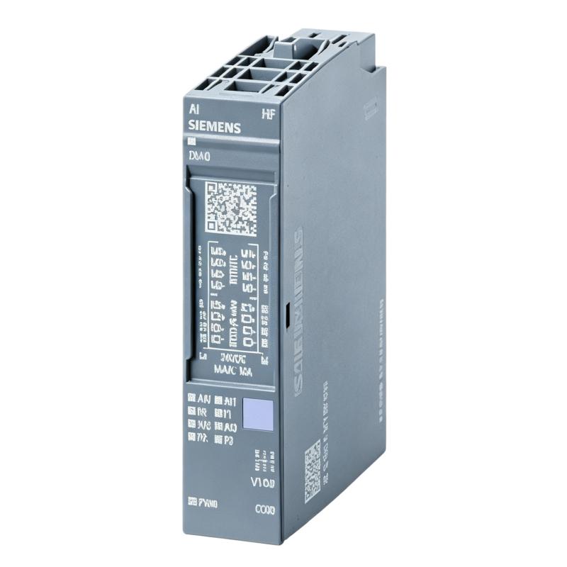
Siemens 6AG1134-6JD00-2CA1 Analog Input Module Troubleshooting Guide (Fault Diagnosis)
Siemens 6AG1134-6JD00-2CA1 Analog Input Module troubleshooting should begin with signal analysis rather than immediate module replacement. Most analog input failures are related to sensor problems, wiring faults, grounding issues, incorrect scaling, or electrical interference.
A structured Fault Diagnosis process helps engineers identify whether the problem originates from the sensor, the field connection, the module, or the PLC application.
Siemens 6AG1134-6JD00-2CA1 Analog Input Module Fault Symptoms
Common symptoms include:
- Analog value suddenly changes
- PLC value differs from field instrument
- Channel diagnostic alarm appears
- Measurement becomes unstable
- Process control output fluctuates
Field example:
A manufacturing line used Siemens 6AG1134-6JD00-2CA1 analog input modules to monitor temperature sensors.
After a cabinet modification:
- Temperature value increased randomly
- Machine control reacted incorrectly
- Sensor display remained normal
The maintenance team initially suspected:
- Temperature sensor failure
- Analog input module damage
Engineers started diagnosis from the complete measurement loop.
Siemens 6AG1134-6JD00-2CA1 Analog Signal Fault Diagnosis Process
Troubleshooting path:
Field Sensor
     |
     |
Signal Cable
     |
     |
6AG1134-6JD00-2CA1 Module
     |
     |
PLC Program
     |
     |
Control Output
Engineers checked:
- Sensor output signal
- Module channel status
- PLC raw data
- Engineering scaling value
Test results:
- Sensor output: Normal
- Module communication: Normal
- PLC value: Incorrect
The fault location was narrowed to the signal transmission section.
Siemens 6AG1134-6JD00-2CA1 Signal Interference Investigation
Measurement results:
Before repair:
- Temperature transmitter output: 8.6 mA stable
- PLC displayed value: Fluctuating
- Variation: Approximately ±12%
Engineers inspected:
- Cable routing
- Shield connection
- Grounding point
- Nearby electrical equipment
The investigation found:
- Signal cable was routed together with motor power wiring
- Electrical noise affected analog measurement
The module was receiving an unstable signal and converting it correctly.
Siemens 6AG1134-6JD00-2CA1 Root Cause Analysis
Final root cause:
Incorrect signal cable installation after maintenance work.
Original condition:
- Analog cable separated from power cables
- Stable measurement
Failure condition:
- Cabinet modification changed cable routing
- Noise increased
- PLC values became unstable
Engineering conclusion:
The analog input module was functioning normally.
The actual fault existed in the external signal environment.
Siemens 6AG1134-6JD00-2CA1 Troubleshooting Repair and Recovery
Corrective actions:
Signal Wiring Repair
Completed:
- Re-routed analog cable
- Restored shield connection
- Checked grounding condition
PLC Measurement Verification
Tested:
- Raw input value
- Engineering conversion
- Process response
Final results:
Before repair:
- Incorrect temperature readings
- Production adjustments required
After repair:
- Stable measurement
- Accurate process monitoring
- Normal automation control restored
Siemens 6AG1134-6JD00-2CA1 Common Fault Diagnosis Methods
Analog Input Value Incorrect
Possible causes:
- Wrong signal range
- Incorrect scaling
- Sensor calibration problem
Diagnostic method:
- Measure field signal
- Compare raw PLC value
- Check configuration parameters
Analog Signal Fluctuation
Possible causes:
- Electrical interference
- Poor shielding
- Grounding problems
Diagnostic method:
- Check cable routing
- Inspect shield connection
- Compare signal at sensor and module
Channel Diagnostic Alarm
Possible causes:
- Sensor disconnected
- Signal outside range
- Wiring error
Diagnostic method:
- Inspect terminals
- Verify sensor power
- Check module diagnostics
Siemens 6AG1134-6JD00-2CA1 Long-Term Maintenance Strategy
For reliable analog measurement:
- Maintain accurate wiring documentation
- Record normal signal values
- Inspect shield connections periodically
- Monitor analog trends
- Verify sensor calibration
A practical engineering rule:
When troubleshooting a Siemens 6AG1134-6JD00-2CA1 Analog Input Module fault, confirm the incoming field signal before replacing the module.
Recommended troubleshooting sequence:
Sensor check → Signal measurement → Wiring inspection → Shield verification → Module diagnostics → PLC scaling review → Final system validation.