Allen Bradley 1746-IH16 Input Fault Diagnosis Guide (SLC 500 Signal Problems)
Understanding Allen Bradley 1746-IH16 Intermittent Input Faults
Allen Bradley 1746-IH16 input faults involving unexpected ON signals or unstable input status should be investigated by checking field voltage, inductive-load transients, common wiring, and PLC input-image behavior before replacing the module. Because the 1746-IH16 is a 125V DC sinking input module, applying troubleshooting methods intended for ordinary 24V DC input modules can lead to incorrect measurements and unnecessary component replacement.
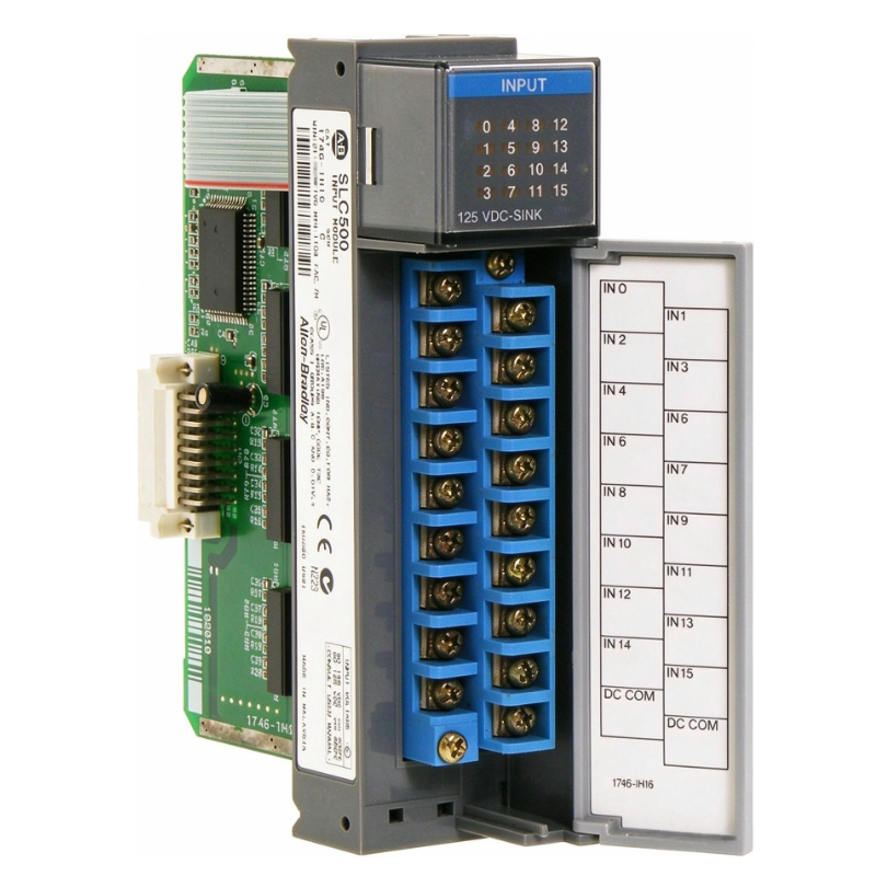
The 1746-IH16 provides 16 discrete DC input channels for Allen Bradley SLC 500 systems. Its operating voltage range is 90–146V DC, and its maximum specified signal delay is 9 ms for both ON and OFF transitions.
A useful Fault Diagnosis process must distinguish between an electrical input problem and a PLC logic problem.
Field Symptoms of Allen Bradley 1746-IH16 Input Problems
Several symptoms can indicate an issue with the 1746-IH16 or its associated field circuit:
An input indicator remains ON after the field device has switched OFF.
A particular input channel changes state intermittently.
The PLC program detects an input that does not match the actual machine condition.
Multiple input channels show abnormal behavior simultaneously.
Input status changes during contactor or solenoid switching.
The module indicator responds, but the machine sequence does not advance.
These symptoms do not automatically indicate an internal module failure.
For example, when an input changes state at the same time a DC contactor is released, the switching transient should be investigated before considering module replacement.
Fault Diagnosis: Why Does the 1746-IH16 Input Remain ON?
One important diagnostic area is the voltage remaining across the input circuit after the field device has switched OFF.
The 1746-IH16 specifications identify a maximum off-state voltage of 20V DC. Voltages between the guaranteed OFF and ON operating regions should not be treated as a valid logic state.
Electrical condition | Diagnostic interpretation |
|---|---|
0–20V DC | Within the specified maximum OFF-state voltage |
20–90V DC | Undefined region; investigate the circuit |
90–146V DC | Within the specified operating voltage range |
The measurements should be taken using the correct reference points specified in the manufacturer's wiring documentation.
Possible causes include:
Leakage through a field switching device.
Incorrect common-terminal connections.
Residual voltage from an inductive circuit.
Damaged field wiring insulation.
An incorrectly selected external switching device.
A digital multimeter reading alone may not reveal short-duration transients. If the fault occurs only during switching, use appropriately rated measurement equipment to capture the voltage waveform.
Engineering Investigation of Inductive Switching Disturbances
Inductive loads can produce reverse-voltage transients when their current is interrupted. These disturbances may affect nearby input circuits or damage components if suppression is not correctly implemented.
Rockwell Automation specifically warns that when the 1746-IH16 input module is connected in parallel with an inductive load, surge suppression should be used across the load.
This is particularly relevant in control cabinets containing DC contactors, relay coils, and solenoid-operated equipment.
Field diagnostic scenario:
Consider an SLC 500 control cabinet in which an input occasionally changes state when a contactor is released.
The engineer should not immediately conclude that the input channel has failed.
The investigation should compare three observations:
The actual electrical state of the field circuit.
The corresponding 1746-IH16 input indicator.
The input bit monitored in the PLC program.
If the abnormal transition occurs simultaneously with contactor release, inspect the suppression arrangement and switching circuit.
After correcting the suppression design, repeat the switching test under normal operating conditions. The input should remain in its intended state throughout the contactor operation.
This is an illustrative diagnostic case, not a claim of a measured repair result from a particular installation.
Diagnosing Incorrect Input Voltage on the 1746-IH16
An incorrect field supply is another possible cause of unreliable input operation.
The 1746-IH16 requires a DC signal within its specified operating range of 90–146V DC. A conventional 24V DC proximity sensor cannot be assumed to operate this input directly.
During Fault Diagnosis, measure the supply voltage at the module input circuit rather than relying exclusively on the power supply display.
Check the following:
DC supply voltage under normal operating load.
Voltage drop across field wiring.
Correct polarity.
Switching-device contact condition.
Voltage at the input terminal when the field device is activated.
A supply measuring 125V DC at the distribution terminal may still produce an inadequate input voltage if there is a high-resistance connection or damaged cable.
The nominal input current is 2.15 mA at 125V DC, increasing to 2.25 mA at 132V DC.
These values are useful when evaluating the electrical characteristics of the field circuit.
Separating 1746-IH16 Hardware Faults from SLC 500 Logic Problems
A module can receive a valid field signal while the machine program continues to behave incorrectly.
For this reason, the input indicator and PLC input image should be evaluated separately.
Observation | Possible fault area |
|---|---|
No input LED, no PLC input | Field supply, wiring, or module circuit |
Input LED ON, expected PLC bit OFF | Slot configuration or address mapping |
LED and PLC bit ON, machine does not respond | Ladder logic or sequence conditions |
Several channels fail together | Common wiring, supply, or backplane |
One channel consistently fails | Terminal connection or individual input circuit |
For example, if channel 5 activates correctly at the module but the ladder program monitors another input address, replacing the module will not solve the problem.
Verify the SLC 500 input address against the actual chassis slot and channel assignment.
SLC 500 Configuration Errors Affecting 1746-IH16 Operation
The 1746-IH16 requires the correct module identification when configuring the system.
Its specified configuration ID code is 0507.
An incorrect module configuration can cause the processor to interpret the I/O arrangement incorrectly or report configuration-related problems.
Check:
Actual chassis slot position.
Configured module identification.
Input image address.
Processor configuration.
Online input status.
Existing force conditions.
For troubleshooting, monitor the relevant input address directly rather than relying only on machine-level status indicators.
Illustrative logic reference:
XIC I:3.5
    OTE B3:1/5
This example monitors input bit 5 in slot 3 and transfers its state to an internal binary address. The actual address must match the installed module location and application program.
Repair and Recovery Strategy for Allen Bradley 1746-IH16
Once the fault source has been identified, corrective action should target the affected circuit rather than replacing unrelated components.
Identified problem | Recommended corrective action |
|---|---|
Insufficient DC input voltage | Restore the correct field supply |
Incorrect polarity | Correct the field wiring |
Inductive switching disturbance | Install suitable surge suppression |
Loose terminal connection | Isolate power and reterminate correctly |
Incorrect input address | Correct PLC configuration or logic |
Damaged field cable | Repair or replace the cable |
Suspected internal channel failure | Perform controlled channel testing and module evaluation |
If an internal module fault is suspected, isolate the field circuit and verify the module using a known-good, correctly rated test arrangement.
Do not apply 24V DC as a substitute test signal to establish normal operation of this 125V DC input module.
Any replacement must also match the electrical characteristics and system configuration of the original installation.
Preventing Repeated 1746-IH16 Input Faults
A successful repair should be followed by a controlled operational test.
Monitor the input status during:
Normal machine operation.
Repeated contactor switching.
Sensor activation and release.
Startup and shutdown sequences.
Simultaneous operation of multiple input channels.
The 1746-IH16 also has temperature-dependent limits on the number of inputs that may be ON simultaneously. For example, at 146V DC, the maximum is 6 points at 30°C and 12 points at 50°C. At 125V DC and 60°C, all 16 points may be ON simultaneously.
These restrictions should be considered when investigating faults that appear only under high-load or high-temperature conditions.
Long-Tail Keywords for 1746-IH16 Troubleshooting
This troubleshooting article covers the following technical search terms:
Allen Bradley 1746-IH16 troubleshooting guide
1746-IH16 input fault diagnosis
SLC 500 125V DC input module problems
Allen Bradley 1746-IH16 input signal failure
1746-IH16 input LED troubleshooting
SLC 500 digital input module repair
1746-IH16 incorrect input status
Allen Bradley 1746-IH16 system configuration
1746-IH16 inductive load protection