Allen Bradley 1746-INT4 Thermocouple Input Module Installation Guide (Wiring & Configuration)
Allen Bradley 1746-INT4 Installation and Application Overview
The Allen Bradley 1746-INT4 thermocouple input module requires correct thermocouple polarity, cold junction compensation (CJC), channel configuration, and electrical isolation to achieve reliable temperature measurements in an SLC 500 control system. Incorrect thermocouple wiring, missing CJC sensors, or unsuitable grounding arrangements can produce inaccurate temperature readings even when the module communicates normally with the PLC.
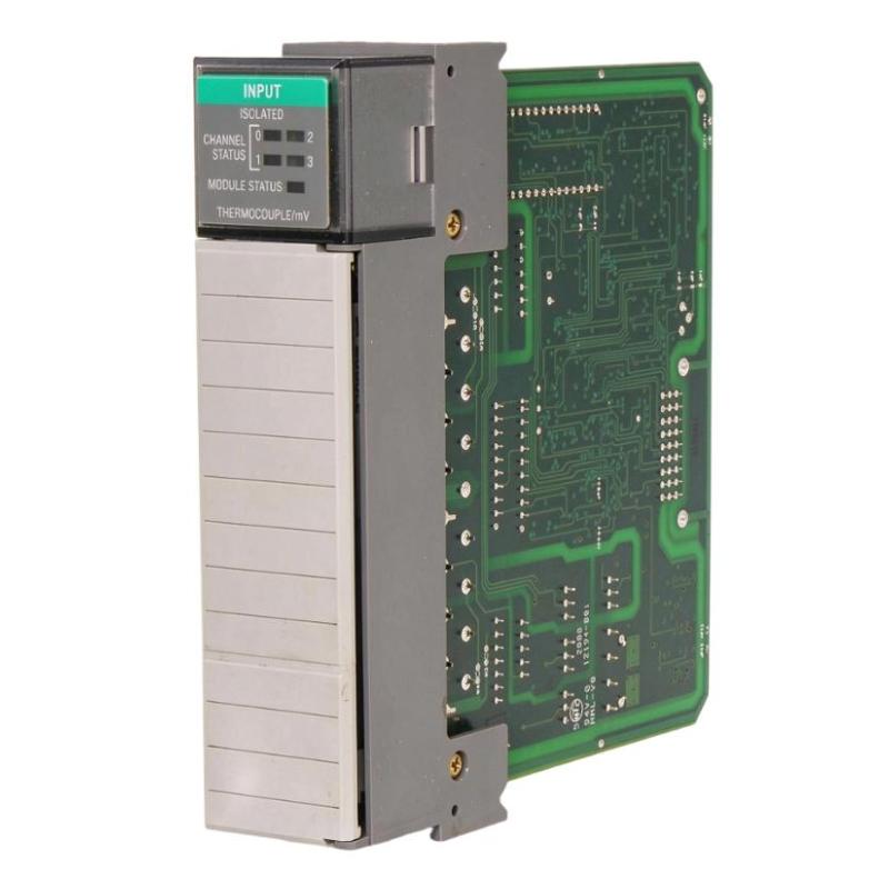
The 1746-INT4 is a four-channel thermocouple/mV isolated input module designed for Allen Bradley SLC 500 systems. Each channel can accept a thermocouple signal or a millivolt analog signal, with individual software configuration.
Typical applications include:
Industrial furnace temperature monitoring.
Plastic extrusion and injection molding temperature control.
Heat treatment equipment.
Industrial ovens and drying systems.
Process heating and thermal protection monitoring.
Multi-zone temperature acquisition.
Unlike conventional digital input modules, the 1746-INT4 converts low-level analog signals into digital values that the SLC 500 processor can use in its control logic.
1746-INT4 Hardware Preparation and Compatibility
Before installing the module, verify the chassis arrangement and available backplane power capacity.
The 1746-INT4 occupies one I/O slot and must not be installed in processor slot 0. It is compatible with supported modular SLC 500 configurations and fixed-system expansion chassis.
Its principal hardware characteristics include:
Parameter | Specification |
|---|---|
Input channels | 4 |
Input type | Thermocouple / mV |
Thermocouple types | B, C, D, E, J, K, N, R, S, T |
Analog input ranges | ±50 mV / ±100 mV |
Channel isolation | Isolated |
Conversion method | Sigma-delta modulation |
Channel bandwidth | 8 Hz |
Backplane current | 110 mA at 5V DC; 85 mA at 24V DC |
Configuration | Software configuration |
The module is a Class 1 I/O module using eight input words and eight output words.
Before installation, calculate the total chassis power consumption. An otherwise compatible module can still cause system problems if the available power supply capacity is exceeded.
Planning Thermocouple Wiring for the 1746-INT4
Thermocouple wiring requires more attention than ordinary discrete I/O wiring because the measurement signal is relatively small.
The engineer should identify the thermocouple type, extension-wire material, polarity, grounding arrangement, and expected operating temperature before connecting the module.
The 1746-INT4 supports different thermocouple types, but each channel must be configured for the actual sensor connected to it.
For example, a furnace monitoring system may use:
Channel 0: Type K thermocouple for furnace temperature.
Channel 1: Type J thermocouple for an auxiliary heating zone.
Channel 2: Type K thermocouple for exhaust temperature.
Channel 3: Millivolt input from an external measurement device.
This mixed arrangement is supported by the module's independently configurable channels.
Do not assume that two thermocouples using different extension-wire materials can share an arbitrary wiring arrangement.
Installing the Allen Bradley 1746-INT4 Module
Before installation, disconnect power from the SLC 500 chassis and isolate field devices connected to the module.
Use ESD precautions when handling the circuit board. Avoid touching the connector contacts and electronic components.
Insert the 1746-INT4 into the selected I/O slot and verify that it is fully seated in the backplane connector.
The removable terminal block should be inspected before wiring. Check that both CJC sensors are present and securely attached.
These sensors are essential for thermocouple temperature compensation. Removing or loosening them can prevent correct thermocouple operation.
The module's terminal block provides connections for four channels, with separate positive and negative signal terminals and associated shield connections.
1746-INT4 Thermocouple Wiring and Grounding Requirements
The correct wiring arrangement is critical to measurement accuracy.
For each channel:
Identify the thermocouple type.
Match the positive and negative conductors to the terminal markings.
Use compatible thermocouple extension wire.
Keep signal conductors away from motor and power wiring.
Connect cable shields according to the manufacturer's grounding instructions.
The quick-start documentation recommends shielded twisted-pair thermocouple extension wire and grounding the shield at one end.
The terminal block ground connection should also be connected to the nearest I/O chassis mounting bolt using the specified grounding conductor arrangement.
Important: The 1746-INT4 provides channel-to-channel isolation, but the actual isolation achieved in an installation can be affected by grounded-junction thermocouples and external wiring connections. Multiple grounded sensors with electrically connected sheaths can defeat the intended channel isolation.
For installations requiring channel isolation, ungrounded-junction thermocouples are often a more suitable engineering choice.
Cold Junction Compensation Setup for Allen Bradley 1746-INT4
Cold junction compensation is one of the most important installation considerations for this module.
A thermocouple measures temperature through the voltage generated by a temperature difference between its measuring junction and reference junction. The 1746-INT4 uses CJC sensors on its removable terminal block to compensate for the reference-junction temperature.
If the CJC assembly is incorrectly installed, damaged, or disconnected, the resulting temperature calculation may be inaccurate.
During installation, confirm:
Both CJC sensors are installed.
Their connections are secure.
The terminal block is correctly positioned.
No CJC terminals have been used for unrelated wiring.
The sensor connection area is free from mechanical damage.
Never remove the CJC thermistors as part of routine troubleshooting.
SLC 500 System Configuration for 1746-INT4
The 1746-INT4 requires software configuration through the SLC 500 programming environment. It does not rely on conventional DIP switches for channel selection.
Configure each channel for its intended thermocouple type or millivolt range.
The configuration should also establish the appropriate temperature scale, input resolution, and open-circuit response.
During System Configuration, verify the module identity and slot assignment.
The module's configuration identification code is 3515 when manual entry is required.
The module uses eight input words:
Input word | Function |
|---|---|
Word 0 | Channel 0 temperature/mV data |
Word 1 | Channel 1 temperature/mV data |
Word 2 | Channel 2 temperature/mV data |
Word 3 | Channel 3 temperature/mV data |
Word 4 | Channel 0 status |
Word 5 | Channel 1 status |
Word 6 | Channel 2 status |
Word 7 | Channel 3 status |
The exact addressing depends on the installed chassis slot.
For example, when installed in slot 1, channel 0 data is available at I:1.0, while its status word is available at I:1.4.
Commissioning and Temperature Measurement Validation
After completing the wiring and configuration, apply power and monitor the module status indicators.
The commissioning engineer should verify the four channels independently rather than assuming that successful module startup proves correct temperature measurement.
A practical validation procedure includes:
Confirming normal module status.
Checking individual channel status indicators.
Comparing the displayed temperature with a calibrated reference instrument.
Checking sensor polarity.
Verifying that the selected thermocouple type matches the physical sensor.
Confirming that open-circuit and out-of-range conditions are detected.
Field commissioning example:
During a multi-zone industrial oven installation, channel 0 may display a temperature that differs significantly from a calibrated handheld thermometer.
The engineer should first compare the thermocouple type configured in RSLogix 500 with the sensor identification. Next, inspect the extension-wire polarity and CJC assembly. If the wiring and compensation are correct, verify the measurement using a suitable thermocouple simulator.
Changing the PLC temperature scaling before checking the physical measurement circuit can conceal the actual installation problem.
1746-INT4 Installation Mistakes That Affect Measurement Accuracy
Several installation errors can produce temperature drift or unstable readings:
Installation problem | Potential consequence |
|---|---|
Reversed thermocouple polarity | Incorrect measurement response |
Incorrect thermocouple type | Temperature conversion error |
Missing CJC sensor | Incorrect compensation |
Poor shield termination | Electrical noise |
Grounded sensor sheaths | Loss of intended isolation |
Long unshielded conductors | Increased interference |
Incorrect channel configuration | Invalid temperature data |
For reliable long-term operation, document the sensor type, channel assignment, extension-wire specification, and calibration history.
Long-Tail Keywords for 1746-INT4 Installation Guide
Allen Bradley 1746-INT4 installation guide
1746-INT4 thermocouple input module wiring
SLC 500 thermocouple module configuration
Allen Bradley 1746-INT4 CJC setup
1746-INT4 temperature measurement commissioning
1746-INT4 isolated analog input setup
SLC 500 four-channel thermocouple installation
1746-INT4 thermocouple polarity and grounding