Allen Bradley 1746-INT4 Temperature Reading Fault Troubleshooting Guide (CJC & Signal Diagnosis)
Why Allen Bradley 1746-INT4 Temperature Readings Become Unstable
Allen Bradley 1746-INT4 temperature reading faults are frequently associated with thermocouple wiring, cold junction compensation (CJC), incorrect channel configuration, and electrical interference. When an SLC 500 system displays fluctuating temperatures, an incorrect process value does not necessarily indicate a defective analog input module.
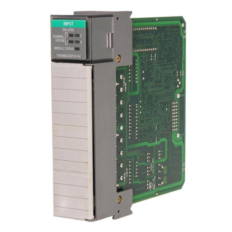
The 1746-INT4 is a four-channel isolated thermocouple/mV input module. It supports thermocouple types B, C, D, E, J, K, N, R, S, and T, as well as ±50 mV and ±100 mV analog signals.
A useful troubleshooting approach is to compare the physical sensor signal, channel diagnostic information, and PLC input data before deciding whether the module requires repair.
Recognizing 1746-INT4 Temperature Measurement Faults
Typical symptoms encountered during SLC 500 temperature monitoring include:
Temperature values fluctuate without corresponding process changes.
One channel consistently reads higher than the actual temperature.
The PLC displays an unexpected zero or extreme temperature.
A channel status LED flashes during operation.
Temperature readings become unstable when nearby motors start.
One thermocouple channel fails while the other three continue operating.
The module reports an open-circuit or configuration error.
The first diagnostic task is to determine whether the problem affects one channel or the complete module.
If only one channel is abnormal, investigate its thermocouple, extension cable, terminal connections, and configuration first.
If several channels develop similar errors simultaneously, examine the CJC assembly, grounding arrangement, chassis power, and environmental interference.
Understanding the 1746-INT4 Channel Status Diagnostic Information
The 1746-INT4 provides individual channel status information through its input image table.
Each channel has a corresponding status word. Four important diagnostic conditions are indicated by the following bits:
Status bit | Diagnostic condition |
|---|---|
Bit 12 | Open-circuit error |
Bit 13 | Underrange error |
Bit 14 | Overrange error |
Bit 15 | Configuration error |
These diagnostic bits help distinguish a sensor circuit problem from a software configuration problem.
For example, if channel 2 reports an open-circuit condition, the engineer should inspect the thermocouple circuit before attempting to recalibrate the module.
The status word also provides a more useful starting point than simply watching the temperature value displayed on the operator interface.
ManualsLib+1
Fault Investigation: One 1746-INT4 Channel Displays an Incorrect Temperature
An individual channel reading incorrectly is a common temperature measurement problem.
Consider a furnace application in which channel 0 displays 420°C while an independent calibrated instrument indicates approximately 350°C.
The engineer should investigate the measurement chain in the following order:
Sensor → Extension cable → Terminal block → CJC compensation → Module conversion → PLC data processing
First, confirm that the thermocouple type configured for channel 0 matches the installed sensor.
Next, inspect the positive and negative conductors. Thermocouple extension cables must use the appropriate material and polarity.
Then check the terminal block and CJC assembly.
If the physical signal is correct but the PLC value remains incorrect, verify the configured temperature scale and the program's data interpretation.
A temperature discrepancy should not be corrected by arbitrarily changing the PLC scaling factor.
1746-INT4 CJC Fault Diagnosis: Temperature Offset Across Multiple Channels
Cold junction compensation problems deserve particular attention when several thermocouple channels show similar temperature deviations.
The CJC sensors compensate for the temperature at the terminal connection point. If their mechanical installation or electrical connection is compromised, temperature calculations may become inaccurate.
The investigation should include:
Inspecting both CJC sensors.
Checking their attachment to the removable terminal block.
Looking for damaged or contaminated contacts.
Verifying that the terminal block is fully seated.
Checking for abnormal heating around the module terminals.
Engineering case scenario:
A four-zone heating system develops a consistent temperature offset across several channels after maintenance work.
Instead of replacing all four thermocouples, the technician compares their readings with an independent reference and inspects the common terminal block assembly.
If all channels show a similar deviation, the shared compensation and terminal environment become stronger diagnostic candidates than four simultaneous sensor failures.
The actual CJC condition should be verified before any recalibration is attempted.
Diagnosing Open-Circuit and Out-of-Range Errors
The 1746-INT4 can detect open-circuit, overrange, and underrange conditions.
An open-circuit error may result from:
A broken thermocouple conductor.
A loose terminal connection.
A damaged extension cable.
An incorrectly terminated junction.
A failed sensor.
An underrange or overrange condition requires checking the configured input type and the actual signal magnitude.
The module supports selectable open-circuit response behavior, including upscale, downscale, or zero.
This means the temperature displayed during a sensor failure depends partly on the configured response. A zero reading should therefore not automatically be interpreted as a genuine process temperature.
For diagnosis, disconnect the suspected field circuit only after following the appropriate isolation procedure. Test the sensor and extension cable independently using suitable thermocouple measurement equipment.
Electrical Noise and Grounding Problems on the 1746-INT4
Thermocouple signals operate at very low voltage levels, making them susceptible to electrical interference.
A temperature value that fluctuates when a variable-frequency drive starts or a contactor switches should prompt an investigation of signal routing and grounding.
The 1746-INT4 provides high common-mode rejection, but good wiring practices remain essential.
Inspect the following:
Whether thermocouple cables run alongside motor power cables.
Whether shielded twisted-pair extension wire is used.
Whether cable shields are grounded at the intended single point.
Whether terminal connections are secure.
Whether grounded thermocouple sheaths create unintended electrical connections.
One important detail is that grounded-junction thermocouples can affect channel-to-channel isolation when their conductive sheaths are electrically interconnected.
For applications requiring electrical isolation between measurement points, evaluate the use of ungrounded-junction thermocouples.
RSLogix 500 Troubleshooting and Input Data Analysis
The SLC 500 processor receives the module's converted measurement values through its input image table.
When the module is installed in slot 1, the input addresses follow this arrangement:
Address | Description |
|---|---|
I:1.0 | Channel 0 data |
I:1.1 | Channel 1 data |
I:1.2 | Channel 2 data |
I:1.3 | Channel 3 data |
I:1.4 | Channel 0 status |
I:1.5 | Channel 1 status |
I:1.6 | Channel 2 status |
I:1.7 | Channel 3 status |
These addresses are examples for slot 1.
During Troubleshooting, monitor the raw input data and corresponding status word in RSLogix 500.
A useful diagnostic sequence is:
IF Channel Status indicates Open Circuit
    Inspect thermocouple and field wiring

IF Channel Status indicates Under/Overrange
    Verify sensor type and input signal

IF Channel Status indicates Configuration Error
    Check channel configuration

IF Status is Normal but temperature is incorrect
    Inspect CJC, wiring, and data processing
The engineer should also check whether the PLC program performs additional scaling, conversion, or mathematical calculations on the original input data.
A correct module measurement can still appear incorrect on an HMI if the application program interprets the value using the wrong data format.
Recovering from 1746-INT4 Module Configuration Errors
A configuration error can prevent an individual channel from operating as intended.
Check the configured sensor type, measurement range, temperature scale, and open-circuit response.
The module's identification code should also match the installed hardware. When manual configuration entry is necessary, the 1746-INT4 uses identification code 3515.
After correcting the configuration, verify the channel status again and confirm that the temperature value responds appropriately to a known input.
Avoid changing multiple channel settings simultaneously. Making one controlled correction at a time makes it easier to identify the original configuration problem.
Repair Strategy for Allen Bradley 1746-INT4 Hardware Faults
If the external measurement circuit and configuration have been verified, investigate possible module hardware failure.
The following table summarizes practical corrective actions:
Fault | Recommended action |
|---|---|
Open thermocouple circuit | Repair wiring or replace sensor |
Incorrect temperature offset | Inspect CJC and sensor configuration |
Unstable readings | Improve shielding and cable routing |
Overrange indication | Verify thermocouple type and actual temperature |
Underrange indication | Inspect signal polarity and input range |
Configuration error | Correct channel parameters |
Multiple channel abnormalities | Inspect terminal block and chassis conditions |
Persistent module diagnostic failure | Evaluate module hardware for replacement |
The 1746-INT4 uses internal diagnostics during startup and operation. A nonrecoverable module-level diagnostic failure requires hardware evaluation rather than repeated changes to the field sensor wiring.
When replacing the module, verify compatibility with the existing SLC 500 chassis and retain the original channel configuration wherever appropriate.
Final Validation After 1746-INT4 Troubleshooting and Repair
A successful repair should be confirmed using an independent temperature reference.
For each channel, compare the PLC measurement against a suitable calibrated thermocouple instrument or simulator.
The validation should cover:
Correct thermocouple type recognition.
Stable temperature readings.
Normal channel status.
Correct CJC operation.
Correct temperature scale.
No unexpected open-circuit or range errors.
Consistent readings during normal machine operation.
Where possible, verify readings at more than one temperature point rather than checking only at room temperature.
The module's input step response can take up to 600 ms under the specified worst-case conditions, so allow sufficient settling time when evaluating changes.
A reliable repair is one that restores correct measurement behavior under actual operating conditions, not simply one that clears the diagnostic LED.
Long-Tail Keywords for 1746-INT4 Troubleshooting
Allen Bradley 1746-INT4 troubleshooting guide
1746-INT4 thermocouple input fault diagnosis
SLC 500 temperature reading problems
1746-INT4 CJC sensor troubleshooting
Allen Bradley 1746-INT4 open circuit error
1746-INT4 temperature measurement offset
1746-INT4 channel status error
SLC 500 isolated thermocouple module repair
1746-INT4 analog input signal diagnosis
Allen Bradley thermocouple module configuration problems