Bently Nevada 32000-28-05-00-100-03-02 Proximity Probe Housing Installation Guide for Turbine Monitoring Systems
Housing Installation Guide for Turbine Monitoring Systems
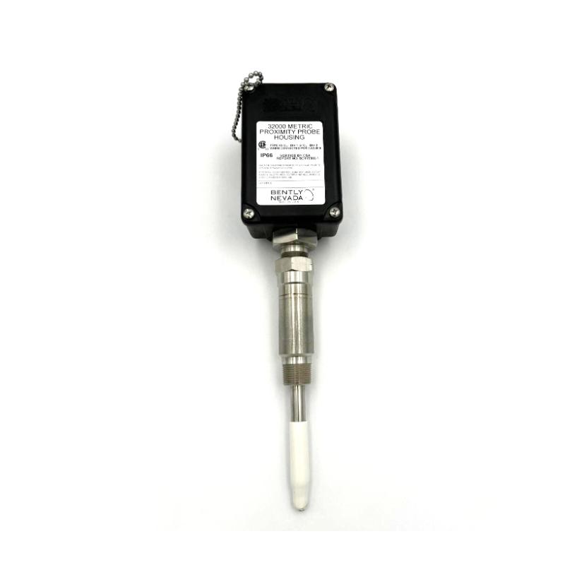
Bently Nevada 32000-28-05-00-100-03-02 proximity probe housing installation problems are often caused by incorrect sleeve alignment and improper cable sealing rather than sensor failure itself. In rotating machinery systems, even a small deviation in probe housing orientation can introduce unstable shaft vibration readings during commissioning.
Bently Nevada 32000-28-05-00-100-03-02 Probe Housing Function in Vibration Monitoring
The Bently Nevada 32000-28-05-00-100-03-02 metric proximity probe housing assembly is typically installed in steam turbines, compressors, and centrifugal pumps where eddy current proximity probes require stable mechanical support and environmental isolation.
Unlike standard mounting brackets, this housing assembly provides:
- Probe positioning stability
- Oil sealing protection
- Cable routing protection
- Mechanical vibration isolation
- Adjustable probe gap configuration
In field applications, this assembly is commonly integrated with:
- Bently Nevada 3300 XL proximity probes
- 3500 monitoring systems
- Axial displacement monitoring channels
- Radial vibration measurement systems
Improper installation directly affects signal linearity and shaft displacement accuracy.
Bently Nevada 32000-28-05-00-100-03-02 Installation Preparation Before Mounting
Before installing the proximity probe housing assembly, field engineers should verify both mechanical and electrical conditions.
Recommended inspection items:
| Inspection Item | Recommended Value |
|---|---|
| Mounting thread condition | No deformation |
| Housing concentricity | <0.05 mm deviation |
| Probe extension cable insulation | >100 MΩ |
| Oil seal integrity | No visible cracking |
| Probe target material | Conductive steel |
In one compressor retrofit project, the original mounting hole contained residual thread-locking compound. The new housing could not fully seat against the machine casing, causing a 0.3 mm probe offset. The vibration trend fluctuated continuously during startup until the mounting surface was re-machined.
Bently Nevada 32000-28-05-00-100-03-02 Probe Housing Wiring and Mechanical Alignment
Correct alignment is more critical than tightening torque alone.
During installation:
- Insert the housing assembly gradually into the machine casing
- Verify probe movement clearance
- Ensure probe tip remains perpendicular to shaft surface
- Route extension cable separately from motor power lines
- Apply shield grounding at one end only
For metric probe systems, the recommended initial gap voltage usually falls between:
- -8 VDC to -12 VDC
Actual values depend on probe type and target material.
Field technicians often make the mistake of adjusting the probe gap before thermal stabilization. On large turbines, shaft centerline movement during warm-up can exceed 0.2 mm, which significantly changes the initial gap voltage.
Bently Nevada 32000-28-05-00-100-03-02 Commissioning Strategy for Stable Signal Output
A stable commissioning process should focus on signal consistency rather than simply achieving acceptable voltage values.
Recommended commissioning workflow:
Cold-State Verification
Confirm:
- Static gap voltage stability
- No intermittent cable noise
- Proper grounding continuity
Low-Speed Rotation Test
At 10–20% shaft speed:
- Observe waveform stability
- Check for periodic spikes
- Verify shaft orbit symmetry
Full-Speed Validation
At rated speed:
- Compare vibration trend with historical baseline
- Confirm no thermal drift abnormalities
- Validate alarm thresholds in monitoring system
In one gas turbine commissioning case, vibration values increased from 4 μm to 38 μm after reaching operating temperature. Investigation showed that the housing locking nut loosened slightly due to differential thermal expansion. After re-adjustment and thread retention correction, vibration stabilized below 6 μm.