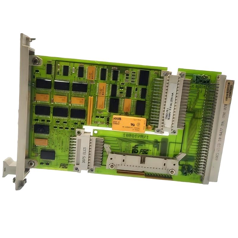
Honeywell 10001/R/1 Vertical Bus Driver Installation Guide for FSC System
Honeywell 10001/R/1 vertical bus driver installation faults are typically caused by incorrect jumper addressing, loose 96-pin connector fixation, or unstable 5 V backplane power, rather than failure of the module electronics. In Honeywell FSC systems, the vertical bus driver (VBD) is the communication backbone between the Central Processor and distributed I/O racks, so mechanical precision is critical.
Honeywell 10001/R/1 Role in FSC Vertical Bus Architecture
The Honeywell 10001/R/1 is a Vertical Bus Driver (VBD) module used in FSC Fail Safe Control systems, responsible for linking:
- Central Processor (CP) rack
- Vertical bus flat cable
- Horizontal Bus Drivers (HBD) in I/O racks
Each VBD acts as a communication node in the FSC topology:
- Up to 14 VBDs per CP system
- Each VBD supports up to 10 HBD modules
- Maximum vertical bus distance: ~5 meters
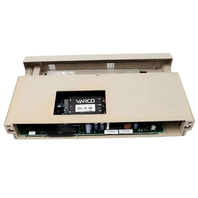
The module is composed of two parts:
- Electronic module (mainboard)
- Wiring part: 10001/A/1 (rack-mounted interface)
In one petrochemical control upgrade, intermittent I/O dropouts were traced to a slightly loose 10001/A/1 connector bolt. After re-torqueing the 96-pin interface, all communication faults disappeared immediately.
Honeywell 10001/R/1 Installation Preparation (Critical Engineering Checks)
Before installation or replacement, engineers should verify:
Rack Mechanical Conditions
- Central rack securely fixed with no vibration
- Slot rails aligned without deformation
- Adequate spacing for airflow
- No stress on flat bus cables
Field observation shows that even low-level vibration can gradually loosen VBD connector torque, leading to intermittent bus loss every 10–30 minutes.
Electrical Preconditions
- Stable 5 V DC supply (backplane power)
- Ripple maintained below ~50 mV peak-to-peak
- Proper single-point grounding of FSC cabinet
- No shared return path with high-power motor loads
In one refinery case, bus instability only appeared during compressor startup due to ground potential shifts between MCC and control cabinet.
Honeywell 10001/R/1 Jumper Configuration (Critical Step)
Incorrect jumper settings are one of the most overlooked failure causes.
J1–J4: VBD Addressing
- Defines VBD number in the system
- Must be unique per vertical bus segment
J5–J6: CP Assignment
- Defines central processor mapping
- Required for redundant FSC architectures
Field Case: Two VBD modules were configured with identical addresses. Result was intermittent I/O mapping conflicts and random channel flickering across multiple racks. After correcting jumper settings, system stabilized immediately.
Mechanical Installation and Vertical Bus Connection
Step-by-Step Field Practice
- Mount 10001/A/1 firmly into 19-inch rack slot
- Align 96-pin connector precisely before tightening
- Apply uniform torque on fixing bolts
- Ensure flat cable is not twisted or under mechanical stress
Critical Failure Mode
-
Partial tightening of 96-pin connector causes:
- Random I/O dropout
- CP unable to detect racks
- Intermittent communication alarms
In one LNG facility, vibration caused gradual loosening of the connector, resulting in periodic system-wide I/O loss every 20 minutes until mechanical re-tightening was performed.
Vertical Bus Communication Behavior (Field Insight)
The vertical bus is highly sensitive to:
- Cable impedance mismatch
- Ground potential differences
- EMI from nearby VFD drives
Even though data is robustly designed, instability usually appears only under dynamic load conditions such as:
- Motor startup
- Compressor ramp-up
- Simultaneous I/O activation
After grounding correction in one offshore platform, communication error rate dropped to zero during 72-hour continuous operation.
Commissioning Strategy (Engineering Practice)
Cold Start Validation
- Verify CP boot sequence
- Confirm all VBD modules detected
- Check LED status consistency across racks
Load Activation Test
- Start with partial I/O load
- Gradually activate full system
- Monitor vertical bus synchronization stability
Dynamic Stress Test
- Simulate full process load
- Observe behavior during peak motor current events
- Check for rack dropout or re-sync events
In one chemical plant, bus instability appeared only when multiple compressors started simultaneously due to shared grounding between MCC and FSC cabinets.