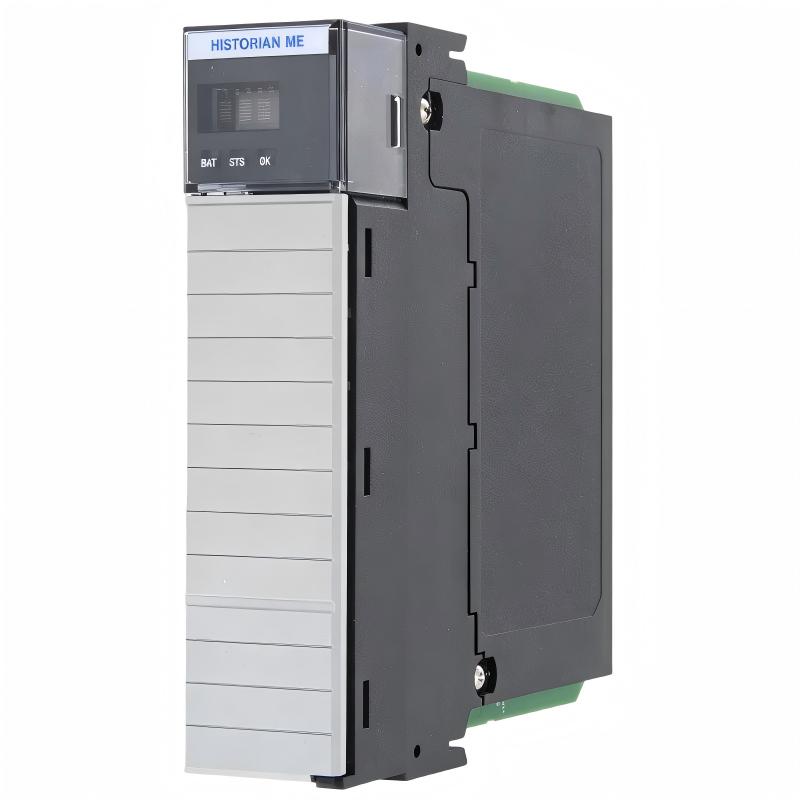
Honeywell 05701-A-0283 Control Card Fault Troubleshooting Guide (Signal Instability & Loop Error)
Honeywell 05701-A-0283 single-channel control card faults are often misattributed to controller failure, whereas field experience shows issues typically arise from:
- Loose edge connectors
- Improper backplane bus power
- Grounding loops or EMI interference
- Thermal stress in the chassis
Honeywell 05701-A-0283 Fault Symptoms in DCS Systems
Common symptoms include:
- Unexpected PID output oscillation
- Intermittent analog input errors
- Channel-specific alarms without process deviations
- Communication timeout with redundant controller modules
In a chemical plant, one 05701-A-0283 card showed repeated loop oscillation at 2-second intervals. The system trending initially suggested sensor drift, but manual measurement confirmed stable process values.
Fault Diagnosis Logic for 05701-A-0283 Control Card
Experienced engineers follow a three-stage field diagnostic process:
-
Mechanical Inspection:
- Check edge connector seating
- Inspect slot for debris or oxidation
- Verify card retention screws
-
Electrical Verification:
- Measure 5 V / 3.3 V supply rails at the card
- Confirm backplane bus voltage stability
- Check grounding continuity
-
Signal Behavior Analysis:
- Inject test input signals
- Monitor PID response on oscilloscope
- Compare with reference loop values
A real refinery case found oscillation traced to a loose chassis mounting bolt that caused intermittent grounding. Correcting it eliminated ±15 mV voltage spikes that were destabilizing the loop.
Common Field Failure Patterns
Connector Seating Issues
- Symptoms: Intermittent analog readings, unexpected alarms
- Fix: Reseat the card and inspect connector fingers
Backplane Power Imbalance
- Symptoms: 05701-A-0283 LED flicker, loop instability
- Fix: Verify DC supply rails and correct load distribution
EMI/Ground Loops
- Symptoms: PID oscillation when nearby high-frequency devices operate
- Fix: Re-route analog cables, install grounding straps
Thermal Effects
- Symptoms: Loop drift during high ambient temperature
- Fix: Ensure proper ventilation and thermal clearance
Recovery and Validation
After correcting faults:
- Confirm stable DC supply to the card.
- Re-run loop tuning verification.
- Observe control signals under full system load.
- Document trend stabilization across temperature cycles.
In one gas turbine plant, voltage ripple reduced from ±20 mV to ±3 mV after grounding correction and slot relocation, eliminating recurring alarms and restoring normal PID operation.