Honeywell 05701-A-0301 Single Channel Control Card Installation Guide for Industrial Gas Detection Systems
Honeywell 05701-A-0301 single-channel control card installation faults are most commonly caused by improper backplane seating or unstable 24 V DC loop supply rather than internal board failure. In System 57 / 5701 architectures, a slight deviation in card-edge contact pressure can immediately lead to alarm misreading or unstable gas concentration display.
Honeywell 05701-A-0301 Control Card Role in System 57 Architecture
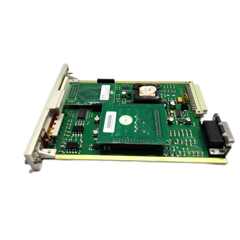
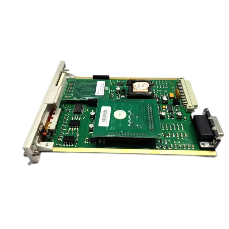
The Honeywell 05701-A-0301 single-channel control card is designed for gas detection and process safety monitoring systems, typically within System 57 racks. It performs real-time processing of a single 4–20 mA input channel and handles:
- Gas concentration signal processing
- Alarm threshold comparison (A1 / A2 / A3 levels)
- Front-panel display logic (25-segment analog + digital readout)
- Fault and inhibit status generation
- Communication with rack backplane and engineering card
In one refinery gas monitoring upgrade, operators observed inconsistent LEL readings on one channel. The issue was not the sensor itself, but a partially seated 05701-A-0301 card causing intermittent reference voltage loss across the backplane.
Honeywell 05701-A-0301 Installation Preparation and System Checks
Before inserting the control card into the rack, field engineers must confirm both electrical and mechanical stability of the system.
Rack and Power Preconditions
- Supply voltage: 18–32 V DC stable
- Backplane connectors: clean, no oxidation
- Rack grounding resistance: < 1 Ω recommended
- Slot alignment: no mechanical deformation
A real commissioning case in a chemical storage facility showed that oxidation on backplane contacts increased loop noise by nearly 12%, causing false “Fault” LED activation on one channel.
Honeywell 05701-A-0301 Card Insertion and Integration Procedure
Unlike generic PLC modules, this card relies heavily on precise mechanical seating and backplane bus stability.
Mechanical Installation Logic
- Align guide rails before insertion
- Push card firmly until latch engagement is confirmed
- Ensure no tilt or partial insertion (critical failure point)
- Lock front panel screws to prevent micro-vibration loosening
In a field case from a LNG terminal, vibration from adjacent compressor skids caused gradual loosening of a partially secured card. Over time, the system showed intermittent “Inhibit” alarms every 30–40 minutes until re-seating corrected the issue.
Electrical Integration Behavior
Once powered:
- Card initializes microcontroller logic
- Reads engineering configuration from system bus
- Activates gas alarm thresholds (A1, A2, A3)
- Begins continuous 4–20 mA signal monitoring
If bus voltage dips below threshold during startup, the card may enter intermittent fault mode even if the sensor signal is correct.
Honeywell 05701-A-0301 Commissioning Strategy (Field-Oriented Approach)
Commissioning should not only validate readings but also verify signal stability under system stress conditions.
Cold Start Verification
- Check display initialization sequence
- Confirm LED status: Power, Fault, Inhibit
- Validate baseline 4–20 mA input stability
Dynamic Signal Test
During controlled gas simulation or signal injection:
- Observe alarm threshold triggering accuracy
- Verify response time consistency (<1 s typical behavior in healthy systems)
- Check for signal jitter or flicker
System Load Stress Test
In one petrochemical commissioning scenario, signal instability appeared only when multiple gas channels were activated simultaneously. Investigation showed shared grounding on the rack power supply, introducing micro voltage fluctuation during peak load.
After isolating grounding paths, signal stability improved and noise dropped from ±18 mV to ±3 mV.