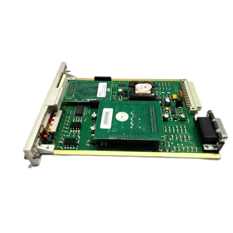
Honeywell 05701-A-0301 Control Card Fault Troubleshooting Guide (Gas Signal Instability & Alarm Drift)
Honeywell 05701-A-0301 control card faults are frequently misdiagnosed as sensor failure, while field experience shows most issues originate from backplane contact instability, DC power fluctuation, or EMI interference inside the rack.
Honeywell 05701-A-0301 Fault Symptoms in Gas Monitoring Systems
Typical symptoms include:
- Intermittent gas concentration spikes
- False A1 / A2 alarm triggering
- “Fault” LED activating without sensor change
- Channel freeze or delayed response
- Inhibit status appearing randomly
In one offshore gas compression platform, the system generated repeated false alarms every time a high-power motor started. Initial assumption was sensor contamination, but manual calibration confirmed stable gas readings.
Field Diagnostic Logic for Honeywell 05701-A-0301
Experienced engineers typically follow a signal-first diagnostic approach, not immediate module replacement.
1. Input Signal Verification (4–20 mA Loop)
Measure loop current:
- Stable 4–20 mA: sensor likely OK
- Fluctuating current: wiring or loop interference
- Sudden drop to 0 mA: open circuit or backplane issue
In one refinery case, loop current dropped intermittently to 3.2 mA during compressor startup, indicating EMI coupling rather than sensor degradation.
2. Backplane and Contact Stability Check
- Inspect gold-finger connectors
- Check insertion depth
- Verify rack vibration impact
A subtle 0.2 mm misalignment in card seating was found to be the root cause of unstable readings in a sulfur recovery unit gas detection system.
3. Power Rail Stability Analysis
Key parameters:
- Nominal: 24 V DC
- Acceptable ripple: <100 mV
- Fault condition: >300 mV ripple
In one industrial gas facility, ripple reached 620 mV due to shared DC supply with solenoid valves. After separating power rails, alarm stability normalized immediately.
Common Field Failure Modes
Loose Card Seating (Most Frequent)
- Symptoms: intermittent alarms, random resets
- Cause: vibration or improper insertion force
- Fix: reseat and mechanically lock card
EMI Interference from Adjacent Equipment
- Symptoms: signal spikes during motor operation
- Cause: poor cable shielding or grounding loops
- Fix: reroute signal cables, improve grounding topology
Aging Backplane Contacts
- Symptoms: gradual drift over months
- Cause: oxidation or wear on connector fingers
- Fix: cleaning or rack maintenance
Field Recovery Case Study
Case: False Gas Alarm on Single Channel
Symptoms:
- Repeated A2 alarm every 20 minutes
- Sensor calibration confirmed stable gas environment
Diagnosis process:
- Loop current stable at sensor side
- Fluctuation detected at backplane interface
- Card slightly loose due to rack vibration
Root cause:
Mechanical loosening of 05701-A-0301 in slot
Corrective action:
- Reinserted and tightened card
- Cleaned connector contacts
- Improved rack vibration damping
Result:
Alarm events eliminated completely; signal stability restored with ±2% variation only.