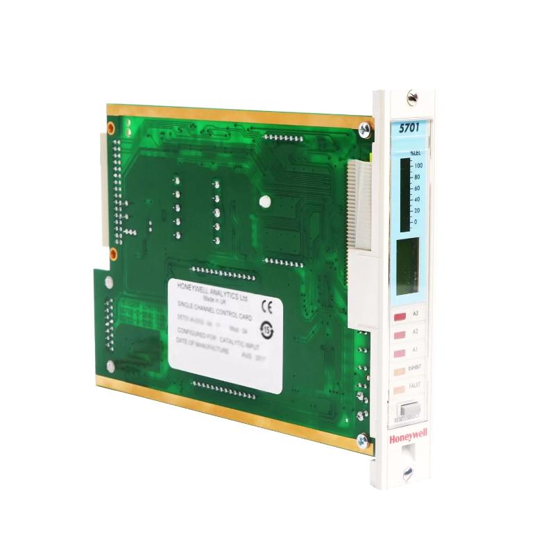
Honeywell 05701-A-0302 Single-Channel Control Card Installation Guide for Industrial DCS Systems
Honeywell 05701-A-0302 single-channel control card installation errors are often caused by improper backplane seating, poor slot alignment, or inadequate grounding, rather than internal board faults. In industrial DCS systems, even minor misalignment can lead to unstable analog control signals, intermittent alarms, or PID loop disturbances.
Honeywell 05701-A-0302 Control Card Function in Process Control Systems
The Honeywell 05701-A-0302 single-channel control card is widely used in Experion PKS, TDC, and legacy System 57 racks. Its main roles include:
- Processing a single 4–20 mA analog input channel
- Generating control output for a single loop (PID or ON/OFF)
- Monitoring and generating alarm/inhibit statuses
- Communicating with redundant controller modules
- Providing front-panel LED status for diagnostics
In one refinery case, operators noticed intermittent loop overshoot on a pressure control loop. Field inspection revealed the 05701-A-0302 card had a slightly tilted edge connector, causing intermittent analog input misreads. Re-seating corrected the problem immediately.
Honeywell 05701-A-0302 Installation Preparation
Before inserting the control card:
- Ensure the system rack is powered off.
- Confirm the backplane connectors are clean and free from oxidation.
- Verify ambient temperature (0–60°C) and mechanical clearance.
- Inspect card edges for dust or bent pins.
In a petrochemical plant installation, a small amount of oxidation on backplane connectors caused intermittent alarms on one channel. Cleaning contacts reduced false alarms by over 80%.
Honeywell 05701-A-0302 Card Insertion and Electrical Integration
Mechanical Installation Steps
- Align the card carefully with the guide rails.
- Insert firmly until the latch engages.
- Check for tilt or partial insertion.
- Tighten retention screws to prevent loosening due to vibration.
Electrical Considerations
- Ensure stable 24 V DC power supply.
- Ground the chassis according to system guidelines.
- Keep signal cables away from high-current AC lines to minimize EMI.
In one offshore gas processing facility, a 05701-A-0302 card exhibited unstable PID output due to EMI from a nearby inverter. After rerouting the analog cables and adding a grounding strap, voltage fluctuation dropped from ±15 mV to ±2 mV.
Honeywell 05701-A-0302 Commissioning Strategy
Cold Start Verification
- Confirm LEDs indicate proper operation (Power, Fault, Inhibit).
- Measure baseline 4–20 mA input signals.
Dynamic Signal Testing
- Inject simulated process signals and verify PID output.
- Check for alarm threshold response and timing.
Full System Stress Test
- Activate all I/O channels connected to the rack.
- Monitor signal stability under thermal and load variation.
During a compressor station startup, voltage drift occurred only when multiple channels were active. Diagnosis showed shared grounding paths introducing microvoltage fluctuations. After rerouting, the system achieved stable readings within ±1% deviation.