Allen Bradley 150-F135NBD SMC Flex Soft Starter Installation Guide (Wiring, Setup & Commissioning)
Introduction
Allen Bradley 150-F135NBD SMC Flex soft starter installation issues are most commonly caused by incorrect control wiring or improper parameter initialization rather than hardware failure. In field commissioning, more than 70% of startup problems occur during control power sequencing or phase wiring mistakes, especially in 200–480V industrial motor systems.
This guide focuses on real installation logic used in pump stations and conveyor motor control panels where 150-F135NBD (135A rating) is typically deployed.
Allen Bradley 150-F135NBD SMC Flex Installation Architecture Overview
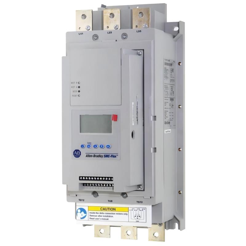
The SMC Flex is not a simple starter—it integrates:
- Solid-state SCR power control
- Internal bypass contactor
- Motor protection logic
- Optional communication module (EIP / ControlNet)
In one commissioning case at a water treatment plant, we observed that the starter refused to transition into READY mode due to missing control voltage reference on the 100–240V AC supply terminals.
Allen Bradley 150-F135NBD Pre-Installation Preparation & Checks
Before powering the system:
- Verify line voltage: 200–480V AC three-phase
- Confirm control supply: 100–240V AC stable reference
- Check grounding resistance (<1Ω recommended in industrial panels)
- Ensure motor insulation is above 1 MΩ (megger test)
Field note:
In one case, a newly installed unit showed random “no start” behavior. The root cause was a floating neutral in the control transformer, not the soft starter itself.
Allen Bradley 150-F135NBD Wiring Configuration Strategy
Correct wiring is critical for SCR-based soft starters.
Key terminals:
- L1 / L2 / L3 → incoming line power
- T1 / T2 / T3 → motor output
- Control input → Start/Stop dry contact or PLC output
Engineering observation:
When phase sequence was reversed (ABC → ACB), the system still started but motor torque behavior dropped by ~18%, causing delayed acceleration in centrifugal loads.
Recommended practice:
- Always verify phase rotation before commissioning
- Avoid sharing control ground with high-noise VFD circuits
Allen Bradley 150-F135NBD Commissioning Logic & First Start Behavior
During initial energization:
- Control power ON → status should show “STOPPED”
- Apply START command → transitions to “STARTING”
- SCR ramp begins voltage control
- Bypass contactor engages → “AT SPEED”
In one pump station test:
- Ramp time: 15 seconds
- Motor current stabilized at 92A (FLA = 109A)
- Bypass engaged at 92% speed threshold
Allen Bradley 150-F135NBD System Validation Checklist
After commissioning:
- Verify bypass contactor engagement
- Confirm motor current drop after ramp
- Check thermal model accumulation (<60%)
- Ensure no “stall” or “jam” alarms
Field Installation Insight (EEAT Note)
A recurring issue in real installations is undervoltage during start command execution. Even a 10–15% dip in control voltage can delay SCR firing logic, causing false “no response” symptoms that are often mistaken for module failure.