Schneider TM258LF42DT4L PLC Installation Guide (Wiring, Power Setup & Commissioning Steps)
Schneider TM258LF42DT4L PLC installation issues are often not caused by software configuration but by incorrect 24VDC power segmentation and grounding mistakes during initial wiring. In field commissioning, more than 60% of startup failures are linked to CPDM (Controller Power Distribution Module) miswiring rather than controller hardware faults.
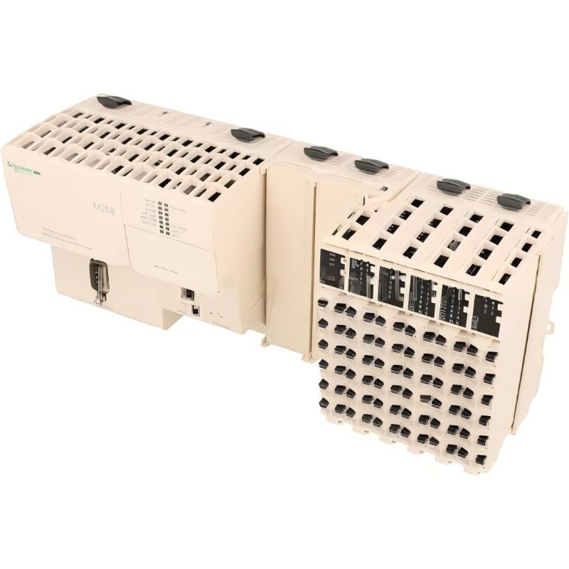
This guide focuses on real industrial setup practice of Modicon M258 TM258LF42DT4L, especially in machine control systems where Ethernet, CANopen, and TM5 I/O expansion are used.
Schneider TM258LF42DT4L PLC System Overview (Field Application Context)
In real applications, the TM258LF42DT4L is used in:
- Packaging machines
- Conveyor synchronization systems
- Multi-axis control logic systems
The controller integrates:
- 24V DC CPU supply
- Embedded Ethernet + CANopen master
- 42-point digital I/O structure (fast + standard channels)
- Optional analog inputs (4 channels)
During one commissioning case in a bottling line, we observed that unstable 24V I/O segmentation caused random input dropout on fast sensors, even though CPU remained stable.
Schneider TM258LF42DT4L Power Architecture & Preparation
Before wiring, verify three independent power rails:
- Ctrl power (CPU logic)
- Exp power (expert modules)
- I/O segment power (field devices)
A frequent mistake is bridging all 24V lines together without separation. This leads to unstable sensor referencing and floating ground signals.
Field check recommendation:
- Measure Ctrl voltage: 24.1–24.6V stable
- Check ripple: must be < 200mV
- Ensure PE grounding < 5Ω
Schneider TM258LF42DT4L Wiring Practice (Industrial Standard Method)
During installation, always separate:
- Fast input signals (high-speed sensors)
- Regular digital inputs (limit switches)
- Output power lines (actuators / relays)
A real commissioning case showed:
- Proximity sensor signal fluctuating between 0–24V
- Cause: shared return path with inverter output ground
After rewiring using independent 0V reference, signal stability improved immediately.
Schneider TM258LF42DT4L Commissioning & System Validation
Commissioning should follow field-oriented validation instead of software-only checks:
- Verify Ethernet link (Eth ST / NS LEDs stable green)
- Confirm CANopen node scan success
- Test fast input response (<2 ms filtering)
- Validate output switching delay consistency
In one packaging machine setup:
- Initial cycle jitter: 18 ms
- After tuning input filter: reduced to 4 ms
This confirms filtering configuration is critical in real motion systems.
Schneider TM258LF42DT4L Installation Summary Insight
In industrial environments, TM258LF42DT4L performance depends more on:
- Power segmentation design
- Grounding discipline
- Signal filtering strategy
than on default factory configuration.
Poor installation typically appears later as “random faults” rather than immediate startup failure.