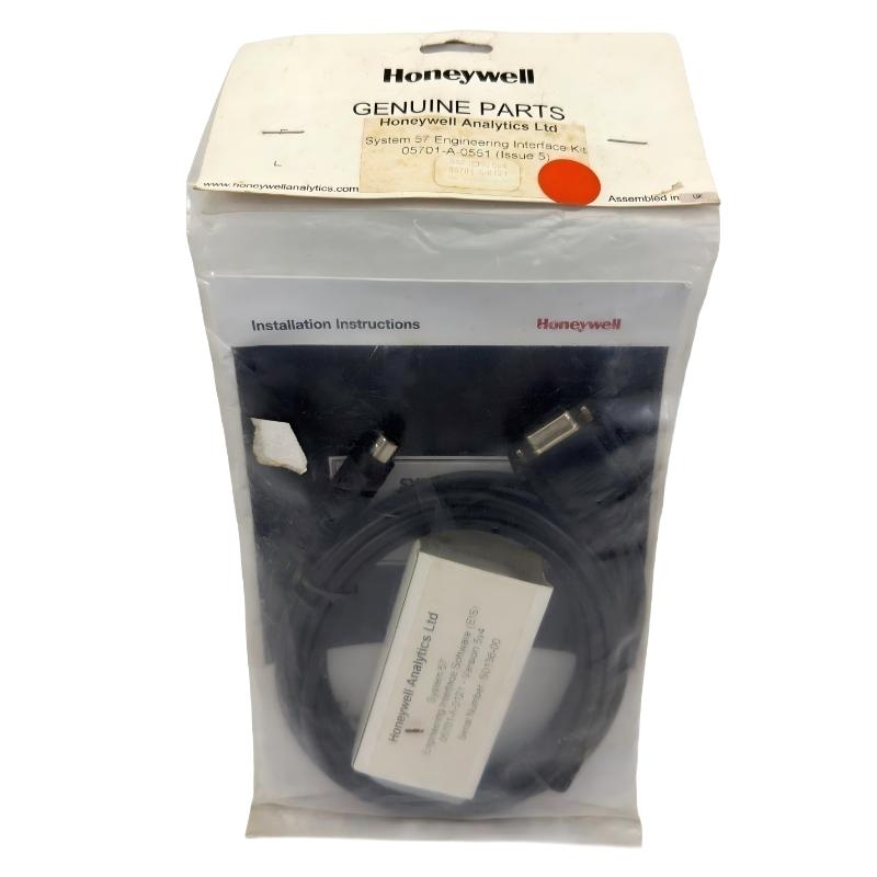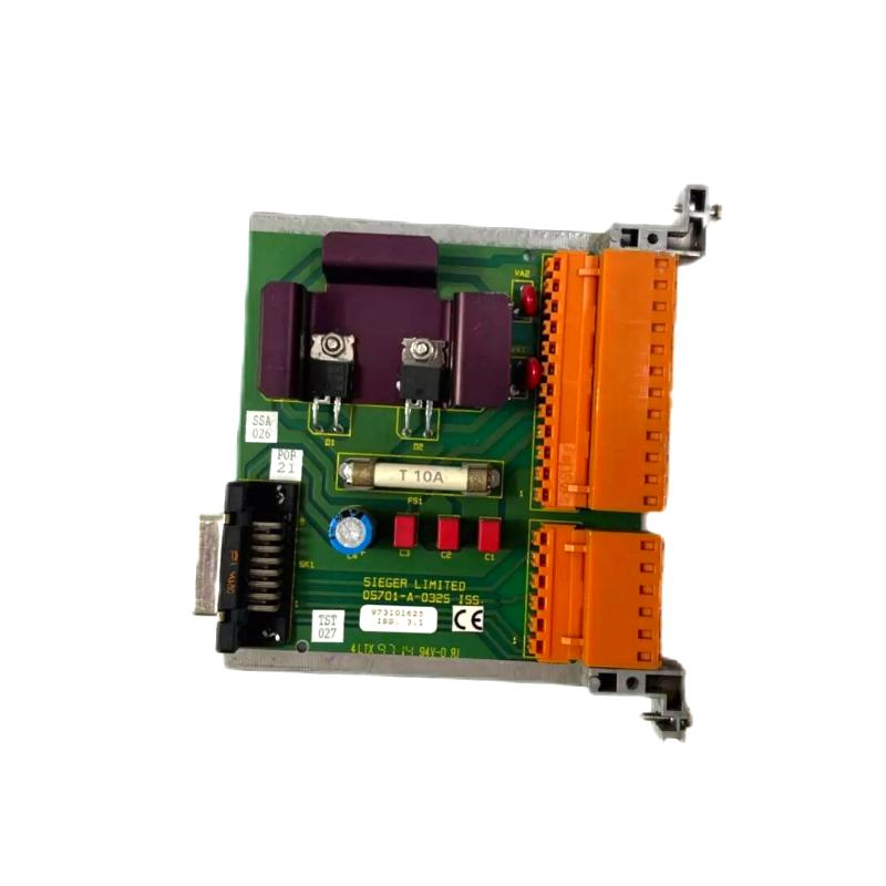
Honeywell 05701-A-0325 Single-Channel Control Card Installation Guide for DCS Systems
Honeywell 05701-A-0325 single-channel control card installation errors are most commonly caused by incorrect slot seating, unstable 24 V DC supply, or inadequate grounding, rather than internal card defects. In industrial DCS racks, even a slight tilt in the card connector can create intermittent analog signal errors, false alarms, or loop instability.
Honeywell 05701-A-0325 Control Card Role in DCS Systems
The 05701-A-0325 is a single-channel analog/digital control card designed for Honeywell Experion PKS, System 57, and legacy TDC systems. Key functions include:
- Processing a single 4–20 mA analog input or digital control signal
- Generating control output for one PID loop
- Alarm threshold comparison (A1 / A2 / A3)
- Communication with redundant controller modules
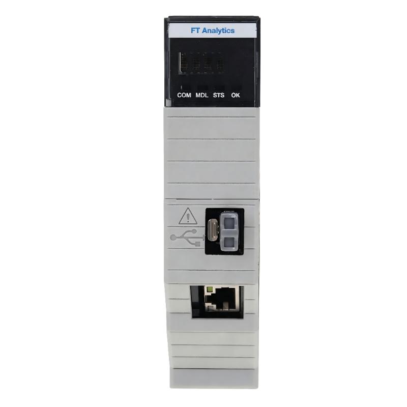
- LED-based status reporting (Power, Fault, Inhibit)
In one refinery installation, operators observed unexpected loop overshoot. Field investigation revealed the 05701-A-0325 card was partially tilted in its slot, causing sporadic analog input misreads. Re-seating the card resolved the instability immediately.
Honeywell 05701-A-0325 Installation Preparation
Before inserting the card:
- Ensure system power is turned off.
- Verify backplane connector cleanliness and inspect for oxidation.
- Confirm slot alignment and mechanical integrity of the rack.
- Check ambient temperature and clearance (0–60°C).
In one petrochemical plant, oxidation on the backplane increased loop noise by ~10%, causing false “Fault” LED activation until contacts were cleaned.
Honeywell 05701-A-0325 Card Insertion and Electrical Integration
Mechanical Installation
- Align card carefully with the guide rails
- Insert firmly until latch clicks
- Check for tilt or partial insertion
- Tighten front panel retention screws to prevent vibration loosening
Electrical Integration
- Ensure stable 24 V DC power supply
- Ground chassis according to system instructions
- Route analog signal cables away from high-current AC lines to prevent EMI
At an offshore gas platform, EMI from nearby VFDs caused unstable PID output on the 05701-A-0325 card. After rerouting analog cables and adding a grounding strap, signal noise decreased from ±18 mV to ±3 mV.
Honeywell 05701-A-0325 Commissioning Strategy
Cold Start Verification
- Confirm LEDs indicate proper operation
- Measure baseline 4–20 mA signal for stability
Dynamic Signal Test
- Inject test signals and monitor PID response
- Check alarm thresholds and response timing
Full System Stress Test
- Activate all channels in the rack
- Monitor signals under full load and thermal variation
In a refinery, voltage drift occurred only when multiple channels were active due to shared grounding paths. After separating grounding paths, signal stability improved to ±1% deviation.