Honeywell 05701-A-0551 Engineering Interface Kit Installation Guide for System 57 Control Rack
Honeywell 05701-A-0551 engineering interface kit installation issues are typically caused by incorrect engineering card positioning, RS232 communication mismatch, or rack backplane power instability, rather than failure of the kit itself. In Honeywell System 57 gas detection systems, the engineering interface is the central commissioning gateway, and any interruption directly affects calibration, configuration upload, and channel diagnostics.
Honeywell 05701-A-0551 Role in System 57 Engineering Architecture
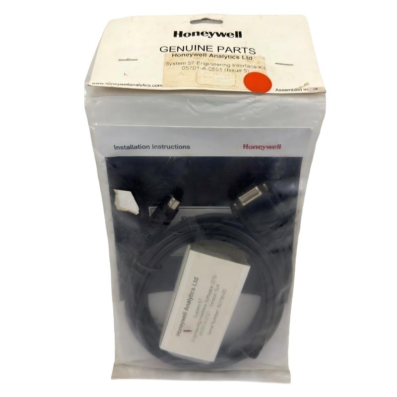
The Honeywell 05701-A-0551 engineering interface kit is used to provide a full commissioning and maintenance interface for System 57 / 5701 racks. It enables engineers to access internal control logic and perform field configuration tasks.
It typically supports:
- System configuration upload and download
- Sensor calibration (zero / span adjustment)
- Alarm setpoint configuration (A1 / A2 / A3)
- Real-time channel diagnostics
- Communication via RS232 / engineering key interface
The engineering card (e.g., 05701-A-0361) is always required in the rack, while the 0551 kit acts as the external engineering access layer.
In one LNG terminal commissioning project, communication failures during calibration were traced to incorrect RS232 baud rate mismatch between laptop and engineering interface kit, causing intermittent “no response” during sensor span adjustment.
Honeywell 05701-A-0551 Installation Preparation (Critical Conditions)
Before connecting the engineering interface kit, engineers must ensure system readiness:
Rack and Hardware Conditions
- Engineering card installed in correct rack slot (right-hand position)
- DC input card stable and providing regulated power
- Backplane communication active and error-free
- No fault or inhibit condition on any channel
Field observation shows that if any channel is in “Inhibit” mode, calibration commands may be blocked by system logic.
Communication Setup Conditions
- RS232 connection cable properly shielded
- Correct COM port mapping on engineering laptop
- Baud rate matched to system configuration
- No grounding loop between laptop and rack
In one refinery case, calibration failure occurred due to laptop ground difference of 1.8 V relative to rack, causing unstable serial communication until an isolated adapter was used.
Honeywell 05701-A-0551 Engineering Connection Workflow
Step 1: Physical Connection
- Connect engineering interface cable to mini-DIN or RS232 port
- Ensure secure locking without mechanical stress
- Verify no cable shielding damage
Step 2: System Unlock Procedure
- Insert engineering key (if required)
- Enable access mode from engineering card
- Confirm LED status changes (system unlock indication)
Step 3: Communication Verification
- Establish serial link with system
- Confirm channel list retrieval
- Validate rack recognition and firmware handshake
Engineering Functions and Field Operation Logic
The 05701-A-0551 allows direct interaction with system-level parameters:
Sensor Calibration
- Zero adjustment (clean air baseline)
- Span calibration using test gas or simulated input
- Drift compensation over time
Alarm Configuration
- A1 / A2 / A3 threshold adjustment
- Delay timing configuration
- Voting logic setup (if multi-channel system)
Diagnostics Access
- Real-time mA signal monitoring
- Channel health status
- Fault history logging
In one chemical plant, drift in multiple gas channels was corrected using engineering interface recalibration, reducing false alarm rate by over 80%.
Commissioning Strategy (Field Engineering Practice)
Cold Start Check
- Verify engineering card LED status
- Ensure system communication bus is active
- Confirm no rack-level faults
Calibration Mode Testing
- Perform zero calibration on selected channels
- Apply span gas and verify response linearity
- Check repeatability across multiple cycles
System Stress Validation
- Perform calibration under full system load
- Verify no communication loss during simultaneous channel updates
- Confirm stable response during compressor or pump startup conditions
In one offshore platform, calibration instability only appeared during high vibration periods. Root cause was cable strain on RS232 line causing intermittent disconnects.