Yokogawa SPW484-53 Power Supply Module Installation Guide (DCS Rack Power Setup & Commissioning)
Yokogawa SPW484-53 power supply module installation issues are usually caused by unstable incoming 24V DC source, poor rack backplane contact, or excessive load distribution imbalance rather than internal module failure. In Yokogawa DCS systems such as FCU and remote I/O stations, most “power abnormal” alarms originate from upstream wiring or grounding problems instead of the SPW module itself.
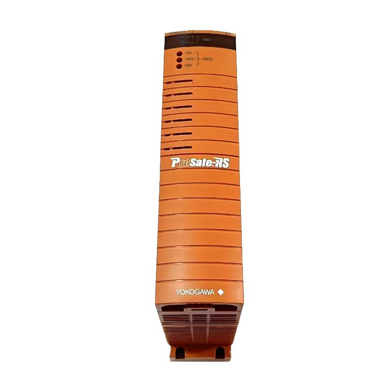
Role of SPW484-53 in Yokogawa DCS Power System
The SPW484-53 is a rack-mounted DC power supply module used in Yokogawa distributed control systems to provide regulated voltage for:
- Field Control Units (FCU)
- I/O communication modules
- Analog and digital signal processing boards
- System-level control and communication backplanes
In real process automation environments, a single SPW module often powers multiple critical control layers. Any instability can cause system-wide alarm propagation, not just single-point failure.
Pre-Installation Engineering Verification
Before installation, field engineers focus on system conditions rather than the module itself:
- Confirm stable upstream DC input supply under load
- Verify rack compatibility and module revision alignment
- Inspect backplane connectors for oxidation or thermal damage
- Check total rack load vs rated power capacity
- Ensure cabinet grounding resistance is within engineering standard
In one petrochemical project, repeated FCU reboot issues were traced to a high-resistance terminal connection upstream rather than the SPW module.
Installation Process in Field Practice
Yokogawa rack power modules require precise mechanical installation:
- Fully isolate system power before intervention
- Inspect rack slot alignment and guide rails
- Insert module slowly to ensure full backplane engagement
- Lock retention mechanism securely
- Restore power and monitor system initialization sequence
- Verify stable DC output across all dependent modules
In one refinery control room case, intermittent rack resets were caused by incomplete seating of the module under vibration conditions.
Commissioning Behavior and System Validation
A properly installed SPW484-53 should show:
- Stable DC output without ripple alarms
- Normal FCU startup sequence without reset loops
- No simultaneous multi-module undervoltage alarms
- Stable operation under load transitions
Field observation example:
- Initial issue: FCU communication drops during compressor startup
- Measured result: DC rail fluctuation between 22.0–24.1V
- Root cause: degraded upstream power distribution terminal
- Fix: replaced terminal block and rebalanced load
- Result: stable 120-hour continuous operation
Common Installation Risks
- Shared unstable DC supply with high inductive loads
- Loose rack locking mechanism causing intermittent contact
- Incorrect load distribution across multiple modules
- Aging cabinet grounding system
- High EMI environment near large motors or VFDs