Yokogawa SPW484-53 Power Supply Module Troubleshooting Guide (Rack Power Fault, Voltage Drop & System Reset Diagnosis)
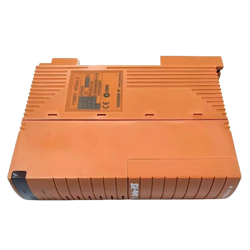
Yokogawa SPW484-53 power supply module faults are typically caused by external power instability, rack backplane contact issues, or system load imbalance rather than internal module failure. In DCS environments, most “power module alarms” are actually caused by field wiring or distribution network problems.
Fault Symptoms in Real Yokogawa Systems
Common symptoms include:
- Multiple I/O modules restarting simultaneously
- FCU communication interruption or reset events
- Rack-wide “power abnormal” alarms
- Intermittent system recovery without maintenance action
- Voltage drop during motor or compressor startup
In one LNG facility, alarms only occurred during large compressor startup cycles, indicating transient DC instability.
Structured Fault Diagnosis Method
Instead of replacing the module directly, engineers follow a layered diagnostic approach:
Input Power Stability Check
Measure upstream DC supply under dynamic load, not idle conditions.
Rack Load Evaluation
Check whether total module load exceeds SPW capacity margin.
Backplane Contact Inspection
Inspect for oxidation, looseness, or thermal discoloration.
Load Isolation Test
Remove non-critical modules to determine if system stabilizes.
In one case, removing a faulty analog module immediately restored full rack stability.
Real Field Case Study
Symptom: intermittent FCU reset every 10–15 minutes
Initial assumption: SPW484-53 failure
Observation: resets occur during valve actuation events
Measurement: voltage drop to ~21.5V DC during load spikes
Root cause: shared DC supply line with high inductive load circuit
Corrective actions:
- Installed dedicated DC power supply for control rack
- Separated power and control wiring paths
- Improved grounding system integrity
Result: system stable for more than 100 hours without reset.
Repair and Recovery Actions
Common corrective actions include:
- Reseating SPW module into rack
- Cleaning backplane contacts
- Replacing unstable upstream power supply
- Redistributing load across multiple power modules
- Fixing high-resistance field wiring connections
In many real cases, hardware replacement is unnecessary once system-level issues are corrected.
Field Engineering Insight (EEAT Perspective)
From Yokogawa DCS field experience:
- Most SPW484-53 faults are system distribution issues, not module failures
- Backplane and terminal aging are major hidden failure sources
- Load transients strongly affect DC stability in industrial environments
- True internal module failure is relatively rare
Correct diagnosis sequence should always be:
Power source → distribution → rack backplane → module → field load