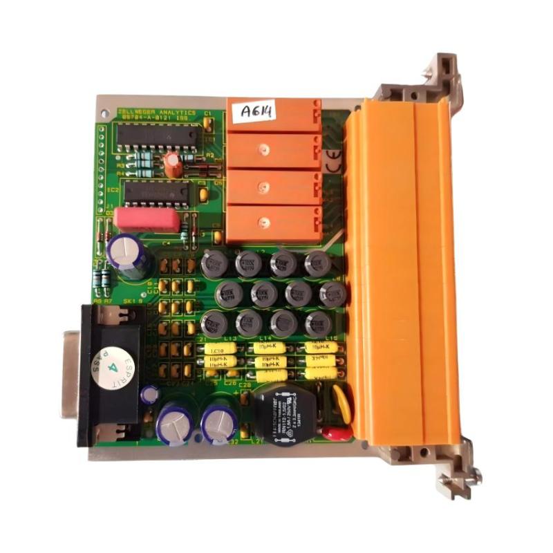
Honeywell 05704-A-0121 Quad Relay Interface Card Installation Guide for System 57 Fire & Gas Control Rack
Honeywell 05704-A-0121 quad relay interface card installation faults are typically caused by incorrect field wiring on relay terminals, backplane contact degradation, or mismatch between control card configuration and relay mapping, rather than internal relay hardware failure. In System 57 / 5704 architectures, the relay interface card is the final execution layer that converts control logic into physical alarm outputs.
Honeywell 05704-A-0121 Role in System 57 Control Architecture
The Honeywell 05704-A-0121 is a Quad Relay Interface Card used in System 57 fire and gas detection racks. It provides the physical relay outputs driven by the associated four-channel control cards.
Its main functions include:
- Providing relay outputs for alarm conditions
- Mapping A1, A2, A3, Fault, and Inhibit signals to field terminals
- Interfacing control logic with external safety systems (ESD, DCS, sirens)
- Supporting configurable relay behavior (latching / non-latching)
Typical configuration includes:
- 4 control channels from fire/gas detector system
- 4 relay groups (Master Fault, A1, A2, A3 depending on configuration)
- Additional remote input and power terminals via backplane
In one refinery fire system upgrade, intermittent alarm output failure was traced to a loose relay terminal screw rather than card failure. After tightening, all alarm outputs restored immediately.
Honeywell 05704-A-0121 Installation Preparation (Critical Checks)
Before installing or replacing the relay interface card, engineers must ensure:
Rack-Level Conditions
- System 57 rack properly grounded (single-point grounding recommended)
- Backplane connectors clean and free of oxidation
- No vibration influence from nearby heavy machinery
- Adequate clearance for relay heat dissipation
Field experience shows that relay contact instability often increases when rack grounding is shared with high-current motor loads.
Electrical Preconditions
- Stable 24 V DC supply
- Ripple within acceptable limits (<100 mV p-p)
- Proper separation between relay output wiring and signal cables
- No shared neutral path with inductive loads
In one offshore platform, relay chatter was caused by voltage spikes from solenoid valves sharing the same DC supply rail.
Honeywell 05704-A-0121 Wiring and Terminal Connection Logic
The relay interface card includes multiple terminal groups:
Relay Output Terminals
- RL1: Master Fault
- RL2: Master Inhibit (or configurable function)
- RL3: Fire Alarm 1
- RL4: Fire Alarm 2
- RL5: Fire Alarm 3
- RL6: Fire Alarm 4
Each relay provides:
- NC (Normally Closed)
- NO (Normally Open)
- COM (Common)
Field Wiring Rules
- Use shielded cables for long-distance relay wiring
- Avoid routing near VFD output or motor cables
- Ensure torque-tightening of terminal screws
- Maintain separation between power and signal wiring
A common field issue is loose COM terminal connection, which results in intermittent alarm output even though control logic is correct.
Honeywell 05704-A-0121 Installation Procedure (Field Practice)
Mechanical Installation
- Align card carefully with rack guide rails
- Push until backplane connector fully engages
- Secure fastening screws to prevent vibration loosening
- Verify no bending stress on backplane connector
Electrical Verification
- Confirm 24 V DC supply stability
- Check relay status LEDs (if applicable)
- Verify continuity of each relay output using multimeter
- Confirm correct mapping from control card to relay terminals
In one LNG facility, partial seating of the relay card caused intermittent “no alarm output” during system test, despite correct logic signals from control cards.
Honeywell 05704-A-0121 Commissioning Strategy (Engineering Approach)
Commissioning should focus on relay behavior under dynamic system conditions, not only static testing.
Step 1: Static Relay Test
- Manually trigger alarm conditions from control card
- Verify relay activation (NO/NC switching)
- Confirm correct terminal mapping
Step 2: Functional Alarm Simulation
- Simulate A1, A2, A3 alarm levels
- Observe relay response time (<1 second typical)
- Confirm correct output isolation between channels
Step 3: Load and Stress Test
- Activate multiple channels simultaneously
- Observe relay stability under system-wide alarm conditions
- Check for relay chatter during motor startup or electrical noise events
In one petrochemical plant, relay instability only appeared during compressor startup due to inductive noise coupling into shared DC supply lines.