Allen-Bradley 1203-FM1 SCANport / Flex I/O Communication Module Installation Guide for DeviceNet Systems
Allen-Bradley 1203-FM1 SCANport communication module installation issues are typically caused by Flex I/O rack backplane misalignment, incorrect key switch positioning, or SCANport cable shielding problems, rather than module hardware failure. In Rockwell Automation architectures, the 1203-FM1 acts as a communication bridge between SCANport devices and DeviceNet/Flex I/O systems, enabling drive and motor control data integration into PLC networks.
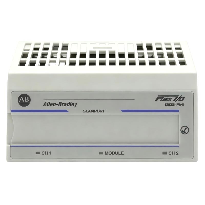
Allen-Bradley 1203-FM1 Role in SCANport & DeviceNet Architecture
The Allen-Bradley 1203-FM1 is a SCANport communication module designed for Flex I/O systems, used to interface SCANport-compatible devices (such as drives) into higher-level industrial networks.
It typically provides:
- SCANport device communication interface
- Integration with Flex I/O terminal base system
- Data exchange between SCANport drives and PLC (via DeviceNet or remote I/O adapter)
- Parameter monitoring and basic control access
Field documentation shows it is used in systems where SCANport drives (e.g., 1336 series) must be integrated into distributed I/O architectures through Flex I/O racks.
System Architecture Insight (Where 1203-FM1 Fits)
In a typical industrial control system:
-
SCANport device (drive or motor controller)
→ 1203-FM1 module
→ Flex I/O backplane
→ DeviceNet / PLC scanner
→ Control system (SLC / PLC / Logix)
This architecture is widely used for legacy drive integration into modern PLC networks.
Field observation: In one retrofit project, a 1336 PLUS drive could not be monitored from PLC until the 1203-FM1 module was correctly seated and SCANport cable shielding was corrected, restoring full parameter visibility.
Installation Preparation (Critical Engineering Conditions)
Flex I/O Rack Conditions
- Terminal base fully seated on DIN rail
- Flexbus connector pushed fully left and engaged
- Key switch set to correct module position before insertion
- No deformation on backplane pins
A partially extended flexbus connector is one of the most common causes of module not being recognized by the system.
Electrical Preconditions
- Stable 24V DC power supply to Flex I/O adapter
- No voltage drop under load conditions
- Proper grounding of rack and cabinet
- SCANport device powered independently (module depends on SCANport device power in some configurations)
Field note: The module may appear “dead” if the SCANport device is not powered, since communication is dependent on SCANport-side supply.
SCANport Cabling Conditions
- Use approved SCANport cable only
- Cable length ideally <10 meters
- Avoid routing near VFD output or high-current conductors
- Ensure shielding continuity at both ends
Improper shielding often results in intermittent data loss or communication timeout errors.
Installation Procedure (Field Engineering Practice)
Step 1: Terminal Base Preparation
- Install terminal base on DIN rail
- Ensure flexbus connector is fully extended
- Verify mechanical locking of adjacent modules
Step 2: Key Switch Positioning
- Rotate keyswitch to correct position (module-specific requirement)
- Incorrect position will prevent module initialization
Field issue: In multiple cases, engineers reported “module not detected” simply due to incorrect key switch alignment.
Step 3: Module Insertion
- Align module pins carefully with base
- Insert until fully seated
- Ensure no bent pins or partial engagement
Step 4: SCANport Connection
- Connect SCANport cable to drive interface
- Ensure locking mechanism clicks into place
- Confirm drive is powered before testing communication
Commissioning Strategy (Engineering Logic)
Step 1: Power-Up Verification
- Confirm Flex I/O rack power stable
- Check module LED status (normal = green blinking)
- Ensure SCANport device is powered
Step 2: Communication Validation
- Verify module appears in PLC configuration
- Check parameter read/write capability
- Confirm SCANport device identity recognition
Step 3: Functional Test
- Read drive parameters (speed, status, fault codes)
- Send basic control commands if enabled
- Monitor communication stability under load
In one steel plant, intermittent SCANport dropout occurred only during conveyor start; root cause was EMI coupling into unshielded SCANport cable.